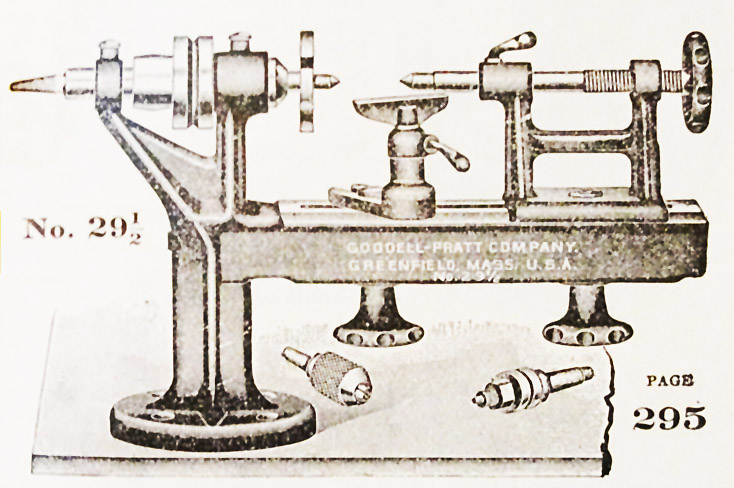
| The original Goodell-Pratt No. 29-1/2 polishing
lathe
was supplied with a graver tool rest and items for buffing wheels and
holding small round objects. |
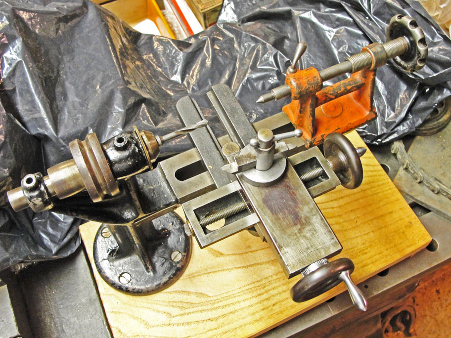
Somewhere I acquired an extremely dirty slide
rest that looked hardly worth the effort of cleaning it up. Once I
exposed the original unblemished, unused surfaces, it became a perfect
match.
|
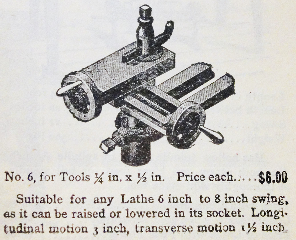
Here's the Montgomery & Co. (New York)
catalog image, page 199, ca. 1900, that is of this exact slide rest.
|
|
|
|
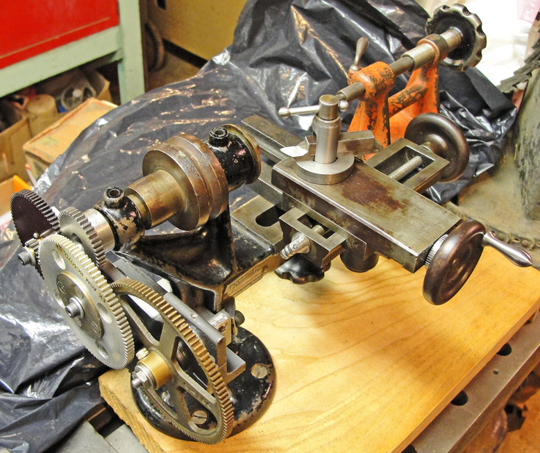
The gears shown below are all from my junk drawers, albeit with center
bushings made from scrap bronze tensile specimens. The shafts on
which
they run are all 0.229+ inch diameter. I proportioned the banjo
after
the one I made for the Sebastian treadle lathe.
|
The brackets & banjo that hold the gears were made from angle iron
and plate steel about 1/4 inch thick. The T-nuts were made from bar
stock. The heavy bracket that fits the extreme left end of the
lathe
was machined from a block of steel and hand fitted by filing, as was
the body clamp shown at right.
|
The two clamping brackets are a fairly close fit to the lathe's
standard, but what saves the situation is the elasticity of the heavy
black paint, a.k.a. japanning. The attachment is quite secure and
does
not wobble or deflect in use.
|
|
|
|
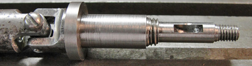
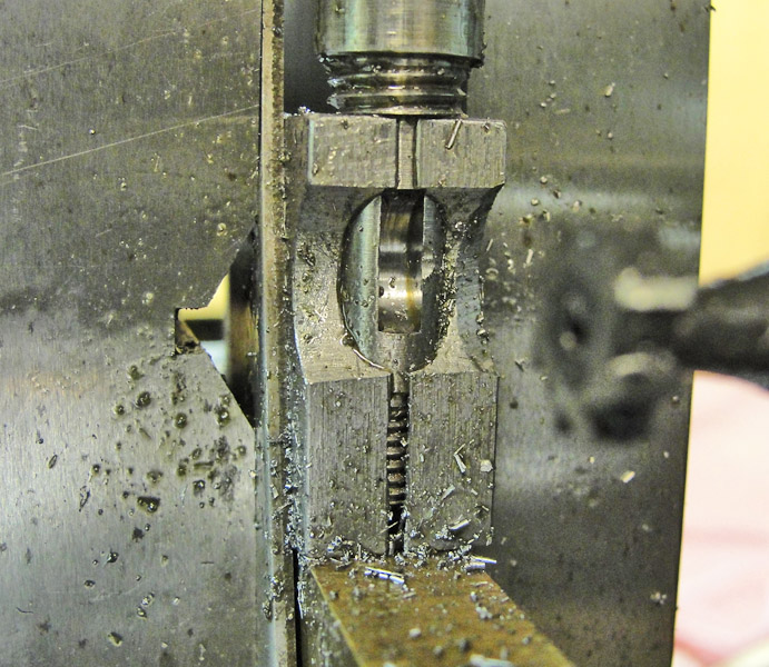
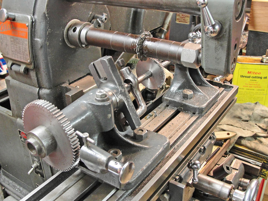
Shown below is the left-hand end of the drive
shaft with its Woodruff keyseat cut. The shorter thread is for a
retaining nut that minimizes end play. The longer thread is for
the thumb nut that retains the screw gear portion of the gear train, so
that it is easily changed for different feeds/threads.
|
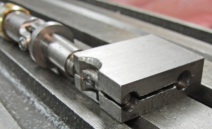
The Woodruff cutter is the 5/16 inch diameter,
3/32 inch wide size that is quite delicate, so I held it in the Atlas
milling machine in a No.2 MT collet and clamped the drive shaft with a
my own special-made, one-time-only holding device.
|
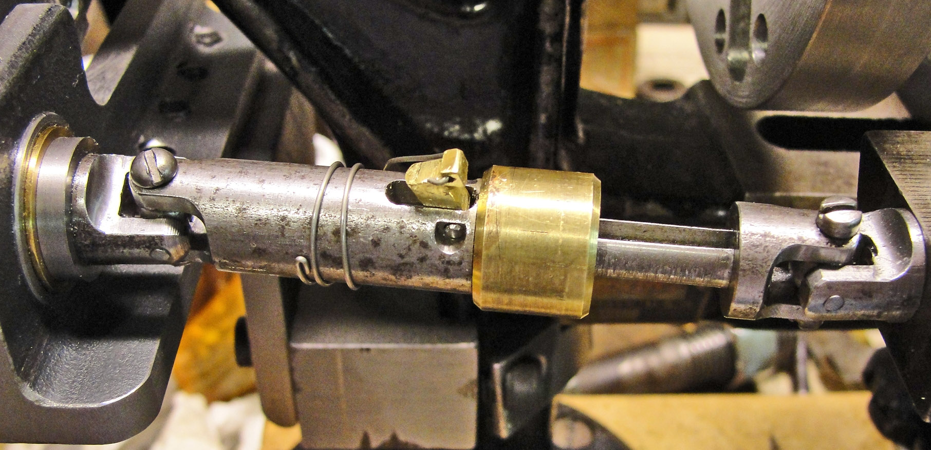
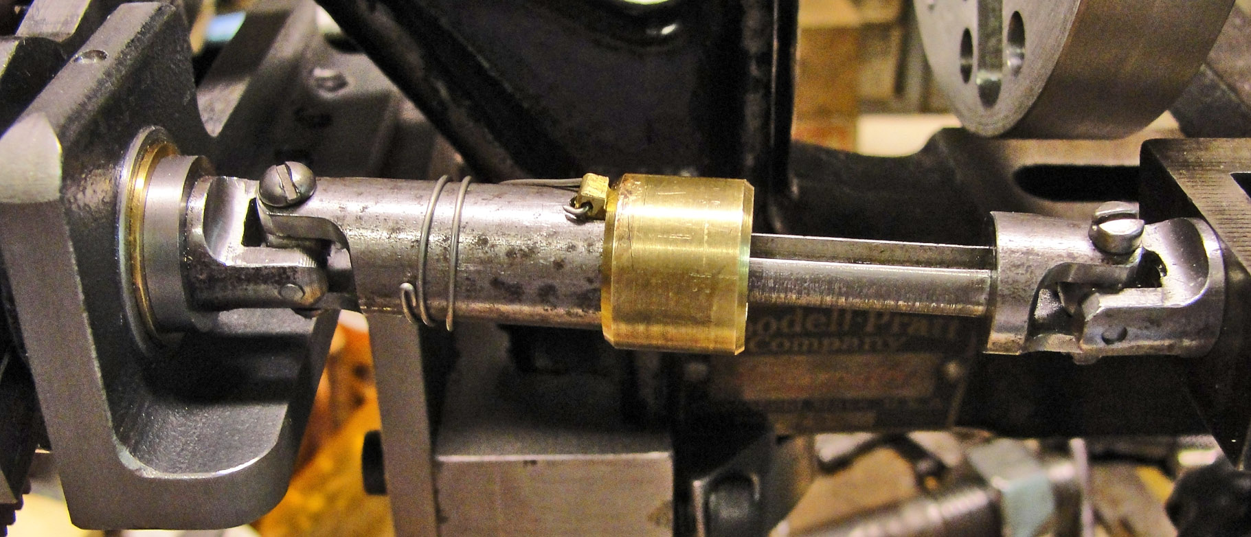
The drive shaft has to be disengaged in a
manner that lets me continue to run the lathe without disengaging the
gear train. The pawl device fulfills this requirement. The brass sleeve
has a friction device (two wire segments) in an annular space, so it
stays wherever it's put. The spring lifts the pawl.
|
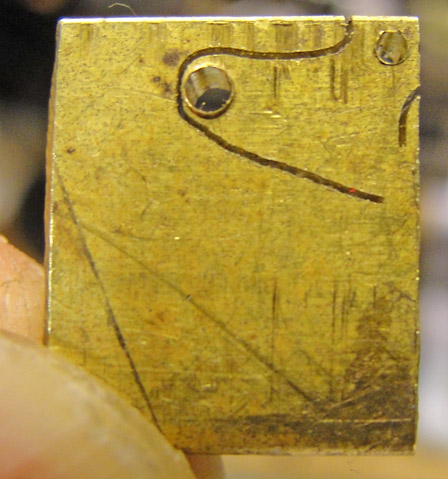
I cut the pawl with a jeweler's saw in one go,
with just a little filing to get it to function properly. It's made
from 1/8 inch thick brass plate.
|
|
|
|
|
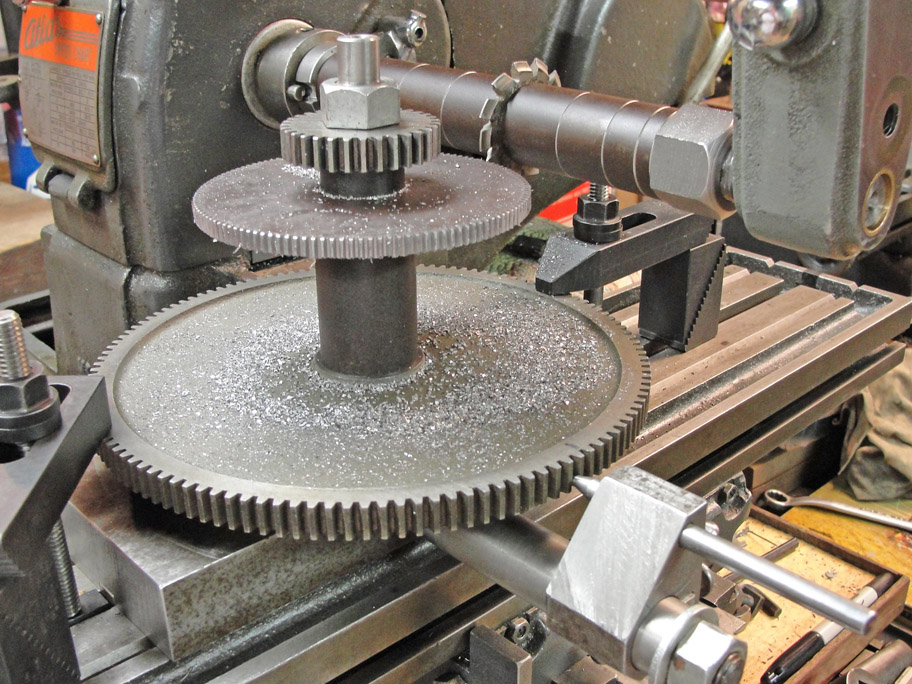
Presently I'm stymied by the lack of a gear
cutter for 35 to 54 teeth, but I do have the cutters that cover 55 to
134 and 26 to 34 teeth; below I'm cutting the 56-tooth gear, using one
I made for the Sebastian treadle lathe as a template.
|
Really large gears would require that I lower
the knee of the Atlas miller too far, so I made a fixture that allows
the template and gear being made to rotate on a common vertical
axis. It's more work to raise and lower the knee in order to cut
each tooth, though.
|
The gear train below, with a 40-tooth stud gear
and 64-tooth screw gear, uses a 56-tooth gear as an idler that also
causes the thread being cut to come out as a right-handed 32 tpi, as
the right-handed feed screw of the compound is 20 tpi.
|
|
|
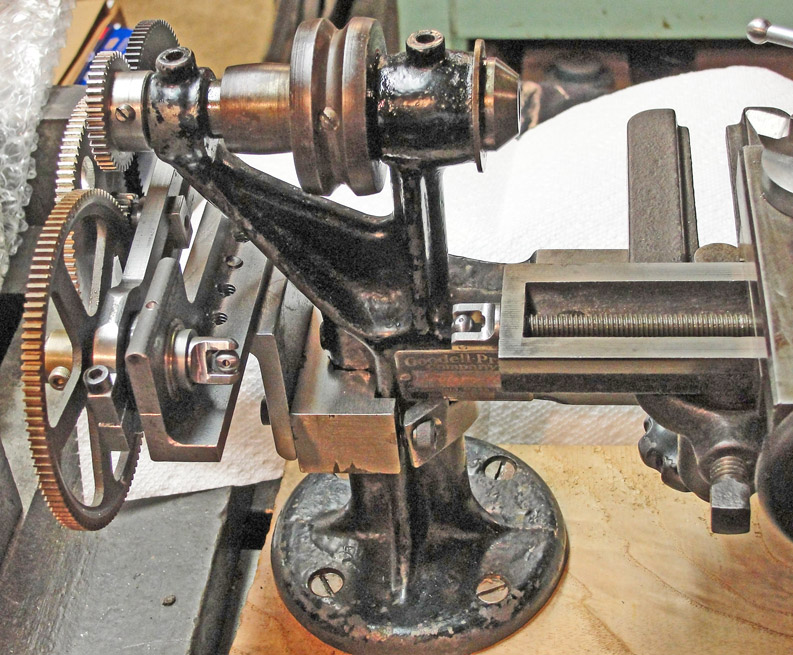
Also of note is the tool post, which incorporates a third
slide so that I can feed the 60-degree thread cutting tool at 29
degrees to the transverse axis so that the chip is cut mainly on one
side of the tool.
|
This lathe's compound rest has only two axes, and even some
three-axis tool rests have no means for setting the single-point
cutting tools feed axis at 29 degrees to the transverse axis as most
machinists know to do in order to get clean threads. The two tool
posts shown here provide that third axis in a way that avoids the need
for angular graduations on the third slide.
|
Perhaps you are wondering how I deal with the
task of setting the point of the cutting tool exactly at the center
height of the lathe ? That's taken care of by the Montgomery
& Co.'s tool slide, which as such an adjustment built into the
base. Just remember to set that before aligning the longitudinal
axis !
|
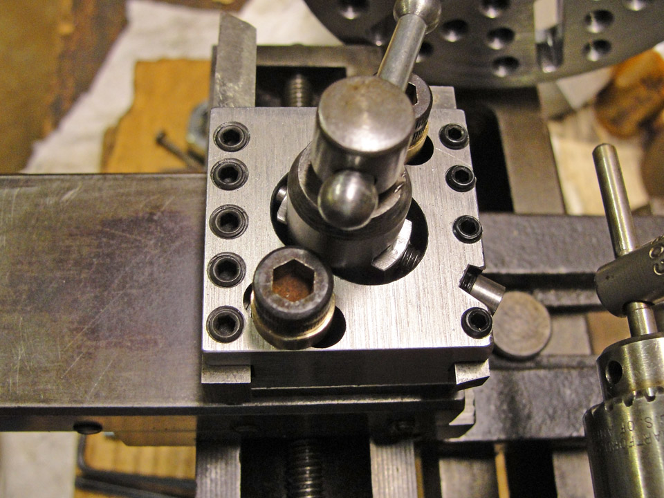
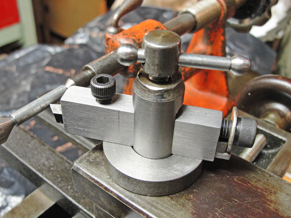 The main clamping screw of the external
threading tool post clamps the outer, channel shaped part of the tool
post. The socket head cap screw clamps the actual tool and holds it
down against a shim that's keyed to the thick washer. The main clamping screw of the external
threading tool post clamps the outer, channel shaped part of the tool
post. The socket head cap screw clamps the actual tool and holds it
down against a shim that's keyed to the thick washer.
The feed screw at right pushes the tool towards the work
at an angle of 29 degrees to the transverse axis of the coupound.
The Vee of the single point tool is rotated 29 degrees
from the feed axis so that proper setting of the tool with respect to
the work also sets the feed axis correctly.
|
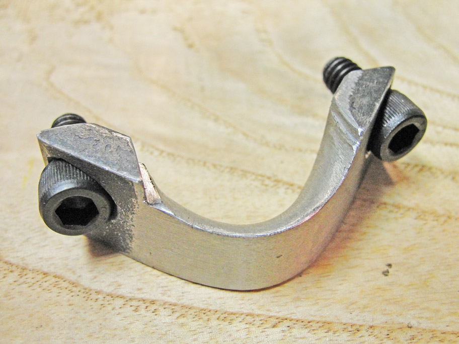
 For the internal threading tool post shown at
left, the third axis of the compound is created by a slide between the
bottom plate of the tool post and the upper part that actually holds
the tool. The bottom plate is clamped with the main clamp, and
the pair of socket head cap screws clamp the upper part to the lower
part. Feed is effectuated by the socket head cap screw whose head
appears at the lower right hand corner of the tool post. The keys
between the upper and lower portions of the tool post run in slots
milled into both parts at 29 degrees to the transverse axis. For the internal threading tool post shown at
left, the third axis of the compound is created by a slide between the
bottom plate of the tool post and the upper part that actually holds
the tool. The bottom plate is clamped with the main clamp, and
the pair of socket head cap screws clamp the upper part to the lower
part. Feed is effectuated by the socket head cap screw whose head
appears at the lower right hand corner of the tool post. The keys
between the upper and lower portions of the tool post run in slots
milled into both parts at 29 degrees to the transverse axis.
|
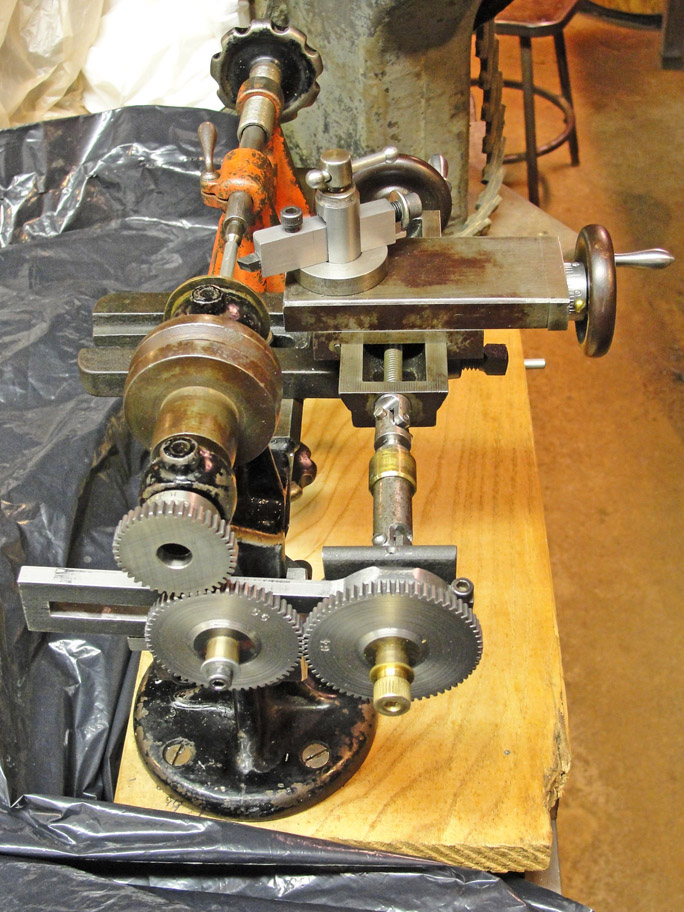
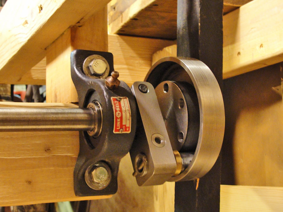
As this is billed as a treadle lathe, I built a
suitable table and tried to invent a foot motion that could coast
without waving the treadle back & forth. This annular drive
fills that bill, as in the image below the center of the annulus is
lined up exactly with the axis of the flywheel's axle. The
flywheel can rotate freely at this position of the treadle (shown as a
mock-up only). Very hard to adjust ...
|
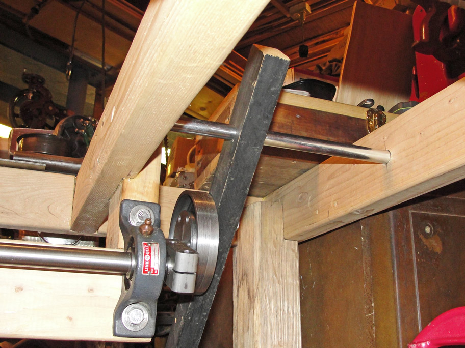
The annular drive can operate in two modes: (1)
With the treadle swinging in a wide arc so that the crank pin (running
on Torrington needle bearings) travels in a full circle; or (2) With
the treadle restricted to a swing truncated at the middle
(freewheeling) position, which causes the crank pin to run in a 180
degree arc, reversing the swing of the treadle arm twice per revolution.
|
I bored the two holes in the crank as exactly as I could
and then made an eccentric sleeve to allow for adjustment on erection.
I also had to allow for adjustment of the position of the
annulus so its arc of swing would pass exactly through the axis of the
flywheel axle. That was by trial & error ... tedious indeed.
Operation was very jerky at first and I only progressed to
an annoying level of jerkiness before I gave it up.
|
 The annular
drive would have worked great, but for this fatal flaw: If allowed to
swing in the full arc, it would randomly try to reverse the flywheel's
direction of motion upon passing the center position if there was the
slightest hesitation. That brought the flywheel to an instantaneous
halt. The annular
drive would have worked great, but for this fatal flaw: If allowed to
swing in the full arc, it would randomly try to reverse the flywheel's
direction of motion upon passing the center position if there was the
slightest hesitation. That brought the flywheel to an instantaneous
halt.
So it had to be restricted to the half swing treadle motion, in
which the treadle would swing with next to no resistance for 90 percent
of the arc, so I had to press the treadle hard during only part of its
motion.
|
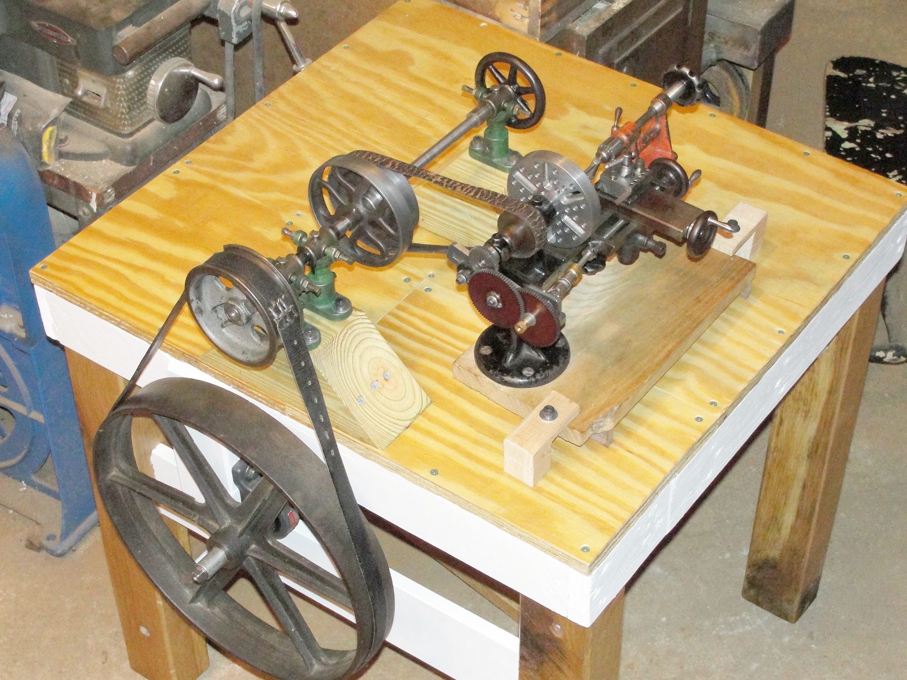
In
the end I just made a simple crank & foot pedal treadle
mechanism which works OK, as the lathe doesn't want to coast very long
anyway, due to the friction in the plain-bearing countershaft. The
shaft hangers are antiques in their own right. At low speed the
spindle turns at eight times the flywheel's speed; at the high speed,
the ratio is about twenty to one. I also made a numbered dial for
the crossfeed; I will eventually do the same for the longitudinal
feed. The drive belt that's presently turning the spindle has a
metal connector that's too large - it hangs up in the narrow clearance
underneath the smaller spindle pulley. Alignment adjustments for the
belts are easy but fussy; the leather belts came from my clothes closet.
I made no irreversible changes to the
Goodell-Pratt lathe; I did make a new spindle
with
a 3/4-10 threaded nose to
hold the four-inch faceplate that I made with thirty 1/4-20 tapped
holes and six Tee slots. I replaced the handles
on the feed wheels of the slide rest; I made no changes to the
flywheel, although I had to get creative to clamp it onto its 3/4 inch
axle. I did find it necessary to raise the tailstock by 0.015 inch
(with brass shims) in order to improve its alignment with the headstock
center. I'm looking for a small chuck that I can fit to the nose
of the spindle. The 30 by 30 by 30 inch bench knocks down to three main
parts that are easily transported. The lathe can be driven by
hand from the little wheel at the right-hand end of the countershaft,
which might make threading a little less stressful.
|
|
|