 Explanation:
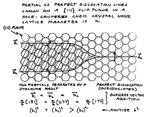
Since a stacking fault in FCC material amounts to a layer of hexagonal
symmetry approximately three atomic planes thick, an FCC metal of low
stability with respect to the hexagonal close packed atomic arrangement
would have a low stacking fault energy (SFE). The diagram at left
describes the effect that the low SFE has on dislocations in the FCC
structure of the material. Explanation:
Since a stacking fault in FCC material amounts to a layer of hexagonal
symmetry approximately three atomic planes thick, an FCC metal of low
stability with respect to the hexagonal close packed atomic arrangement
would have a low stacking fault energy (SFE). The diagram at left
describes the effect that the low SFE has on dislocations in the FCC
structure of the material.
The dislocations in the FCC structure of any metal are split into two
partial dislocations, which together have a lower strain energy than
the undissociated perfect dislocation, even though the two partials
have to be separated by a band of stacking fault, as shown here.
Look at it this way: The close packed planes slip over one another in
two steps. In the first step, the motion is half a step to the
right and forward, and in the second step, the motion is half a step to
the left and forward. The atoms simply follow a zig-zag
path. Dislocations are the mechanism whereby the close packed
planes of metals can slide over one another, not all at once, but a
little bit at a time, and still not have much metal in an in-between
condition. The actual dislocation consists of the edge of an
extra plane of atoms inserted in the structure. Above and below
the edge of this extra atomic layer, the structure looks the same in
all directions. Only at the very edge of the extra plane is there
any disurbance to the orderly array of atoms in the crystal.
|
| The
partial dislocations are very widely spread apart in this low SFE alloy
because there is little penalty for a wide separation of the two
partials brought about by their mutual repulsion (strain energy).
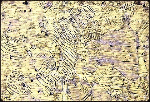
The
separation is so large that the first partial dislocation can get away
from its companion and thereby create a macroscopically visible band of
stacking fault extending clear across a grain. This stacking
fault
then acts as a barrier to other dislocations which try to cut through
it. Consequently, Hadfield's austenitic manganese steel work
hardens
extremely rapidly. It is used as a hard facing material and is
welded
onto the wearing surfaces of railroad switches, bulldozer blades,
hammer mills, and so on. Conveniently, natural cooling after
welding
onto a massive substrate gives sufficiently rapid cooling that it
avoids carbide precipitation, obviating any need for subsequent heat
treatment. |
SUMMARY: Although this
has not been an exhaustive survey of high alloy steels, the chosen
examples serve to illustrate that the analysis and interpretation of
their microstructures and metallurgical failures are not much more
complex than for simpler alloys. It is important to realize that
many more phases (often of complex crystal structures) are involved, so
past experience and attention to published literature on the structures
are especially helpful.
Continue to the
next lesson in Cast Irons, High
Alloy Steels, and
Superalloys.
Return to the main Introduction.
|