Microstructures
by
George
Langford, Sc.D., Massachusetts Institute of Technology, Cambridge, MA,
1966
Copyrightę2005 by George Langford
Low Alloy Steels - Lesson 1 -
Eighth specimen

|
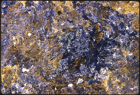
This is unusually coarse pearlite in a eutectoid (0.8%
carbon) steel. The colors in the first picture at left, shown at
100X with a Nital etch, are
interference effects.
The apparent interlamellar spacings act as
diffraction gratings for the reflected light.
The opalescence of
the specimen when viewed with the naked eye gives pearlite its
name. Most of the other names of microconsituents in steel were
chosen to honor early researchers in the field of metallurgy.
|

|
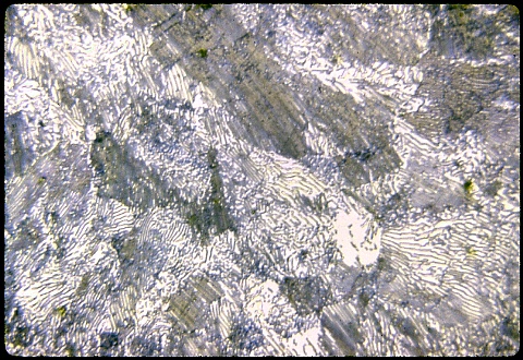
At 500X at left you can now resolve all but the finest of
the apparent interlamellar spacings. The finest spacings seen
here were sectioned at right angles to the planes of the lamellae, and
so they are the actual spacings. The others were mostly sectioned
at shallower angles. The angle of sectioning cannot be determined
without tedious serial sectioning of the specimen. There can also
be a distribution of actual spacings.
The transmission electron
microscope is of great help here; see below.
|

|
Transmission electron micrograph
of pearlitic
steel wire cold drawn to 98% reduction of area.
Here
we avoided the usual sectioning error by growing the pearlite from
austenite unidirectionally in a steep temperature gradient. That
aligned most of the pearlite parallel to the wire axis, so we could
then study the effect that wire drawing has on the microstructure of
the pearlite.
The wide variations in interlamellar spacing are
the result of an interaction between the preferred crystalline
orientation of the ferrite and original orientation of the ferrite with
respect to the pearlite lamellae. |
SUMMARY: Be sure
you understand the workings of the iron - cementite phase diagram so
that the sequence of formation of the microconstituents of these
specimens makes sense. Their arrangements and morphologies are
quite sensitive to the details of the heat treatment, processing, and
chemistry by which they were formed (or failed !).
|


