adapted to a
Bausch & Lomb Research (I) metallograph
by George Langford
| When my consulting company (Amenex Associates, Inc.)
had commercial laboratory space, we used a really nice Reichert MeF2
metallograph that had a Nomarski differential interference contrast
accessory as well as a cute little microhardness testing device.
After the Enron debacle, it became uneconomical to keep the lab open,
and I had to give up the Reichert metallograph for lack of space.
However, I was able to assemble a working Bausch & Lomb Research
(I) metallograph from pieces obtained on eBay (but without the
extravagant optical bench) and I've wanted to work out a way of fitting
Nomarski DIC to that instrument. Here's my present progress, as
of January 21, 2007. The Bausch & Lomb Research (I) metallograph has polarized light as standard because it uses a Foster prism as the vertical illuminator. In order to defeat the polarized light, one has to place a quarter-wave plate in the optical path (the "B" setting of the illuminator). Therefore, there is no way to change the polarized light except to turn it on (crossed to extinction) or off (quarter wave plate). There is no in-between setting. That appears to present no handicap to the use of Nomarski differential interference contrast in my Bausch & Lomb Research (I) metallograph. Bausch & Lomb later made available a complex accessory for providing the intermediate settings. The Reichert metallograph's DIC accessory incorporated axial as well as transverse adjustments for its Nomarski prism, but the setup described below does not permit axial movements of the prism. However, the prism appears to be symmetrically placed between the nose mount and objective lens mount as originally applied by Olympus, as it still is in my setup, and so I do not miss that adjustment. Moving the Nomarski prism, using the thumbscrew seen in the foreground below, changes the interference colors and image offset (height contrast) when looking at a flat, polished surface, and it is possible to see both positive (hills) and negative (opposite to the actual topography) height contrast on these flat surfaces. However, the images shown below of a lamellar eutectoidal microconstituent show more variable and pleasing effects of Nomarski DIC contrast. The Foster prism is extremely efficient at transmitting light, so image brightness is not an issue. |
 |
 |
 |
| Assembled
Nomarski DIC apparatus in place on the Bausch & Lomb Research (I)
metallograph. Note the settings of the illumination system:
B=bright field & PD=polarized light. |
One of
the normal Bausch & Lomb bright field/dark field objectives is
shown above next to the Nomarski adapter fitted to a modified surplus
B&L bayonet mount. The Nomarski setup appears to increase the
tube length of the objective by about 8 millimeters. |
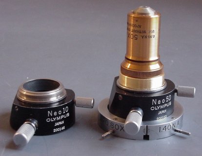
I
obtained two Olympus Nomarski DIC prisms on eBay, but I cannot tell
whether they are really any different, because my B&L 10X bright
field/dark field objective (borrowed from a Bausch & Lomb Balphot
(I) metallograph) makes good-looking Nomarski images using the 50X
Nomarski prism shown above, right. |
 |
 |
 |
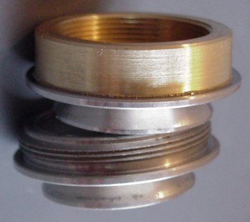
| When
installed on the usual Olympus transmitted-light microscope, the DIC
prism is located after the objective lens, so the unmodified adapter on
the bottom in the image above actually screws into the microscope's
nosepiece. In the metallographic application, the DIC prism is
simultaneously before and after the objective and is physically located
below the objective lens, so the modified adapter, also shown above,
has been given a female RMS thread. The brass insert fits into a
recess machined into the original adapter and is fastened with
Gorilla® glue. |
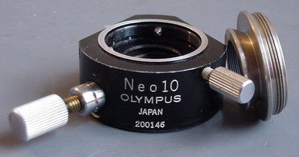
The
two Olympus Neo DIC prisms (10X shown above) were obtained on eBay for
$50 plus shipping each. At first, I thought that I could use the
original mount's centering screws to center the mount, but I discovered
that the screws were Lok-Tite'd in place by the manufacturer,
presumably to preserve the factory setting. I could not budge
these screws, one of which is shown at top center above, the other
peeking out from the left. Therefore, I modified one of the Bausch & Lomb bright-field bayonet mounts (shown at right above) so I could use that mount's centering screws instead. In spite of those modifications, the B&L bayonet mount could still be used to hold its original 80X, 1.40 NA oil immersion lens if that is ever found. The bright-field/dark-field bayonet mounts would be unusable in the present application because a glass insert occupies the place for the screws. |
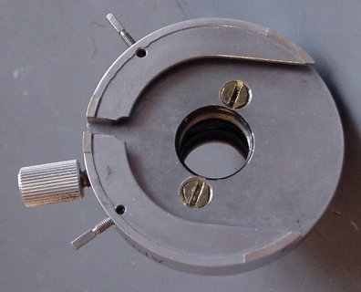
The
bottom view of the modified Bausch & Lomb objective mount is shown
above. The two brass screws on each side of the central aperture clamp
a ring which screws into the bottom of the Olympus DIC mount (10X shown
at left above) using the one inch, RMS threads of the Olympus
mount. That permits me to screw the mount onto the B&L's
bayonet to a convenient position and then clamp it there using the two
No. 4-40 screws shown above. The locating shoulder for the
mount's original Olympus objectives is thereby brought to a bearing
against a recess machined into the top of the Bausch & Lomb bayonet
adapter. |
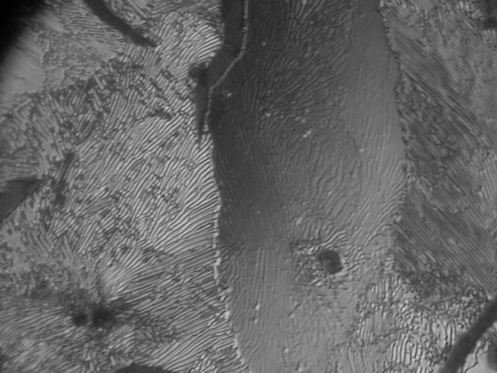
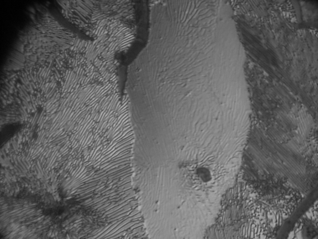
| Each
of the four images below was made with Nomarski DIC using the present
apparatus and the Bausch & Lomb 50X apochromatic objective lens
(corrected for a 215mm tube length). The subject of the three
identical microstructures was pearlitic grey cast iron, but the
contrast was adjusted for each image by moving the image-shearing
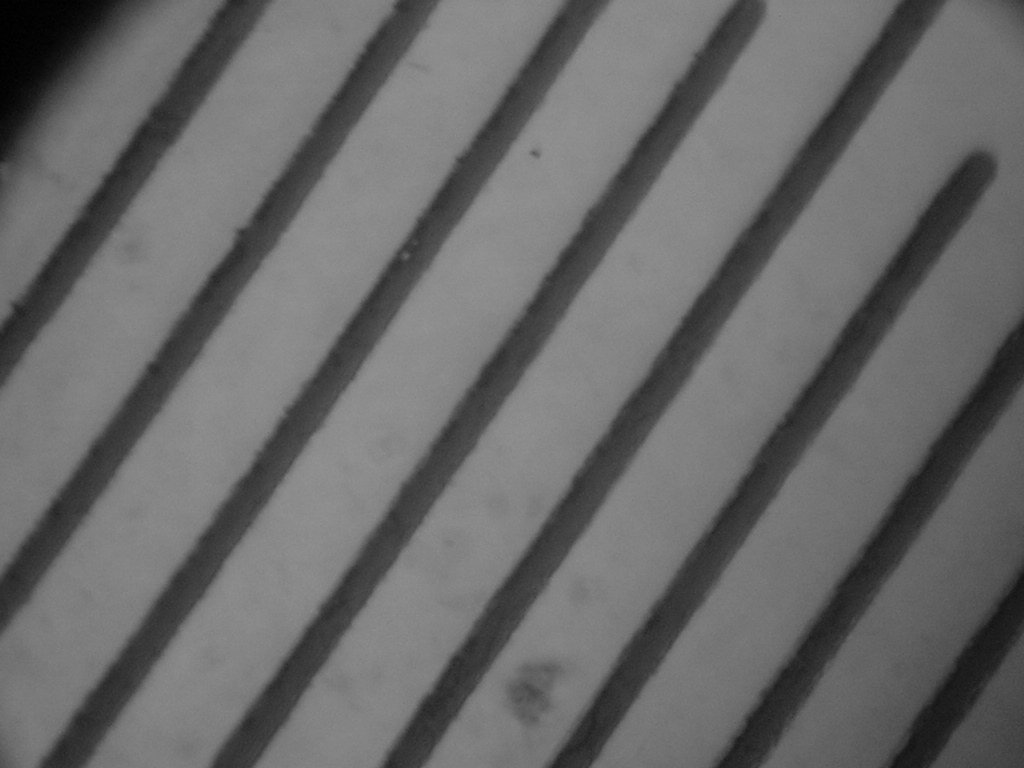
wedge. The stage micrometer was imaged with the same magnification settings; the ruled line spacing is 0.01 millimeter. When the images are displayed with a 140 mm diagonal, the magnification is about 1500X, half again larger than the optimum 950X (1000 times the 0.95 numerical aperture) of the objective lens. The camera is a Sony Mavica with an Optem No. 257011 microscope adapter; the camera's lens has to be zoomed to get the microscope image to fit the CCD format; that is why there is a dark area in the upper left hand corner of each image below. Nevertheless, the imaged area represents at least half the field of view of the 15X wide-field eyepieces used in the microscope's binocular viewer. These are all unedited, full-frame, 1024 by 768 pixel images, which you can view separately at a 1:1 pixel ratio by right-clicking each one. |
 |
 |
 |
 |