|
|
|
The chuck base wouldn't unscrew ...
|
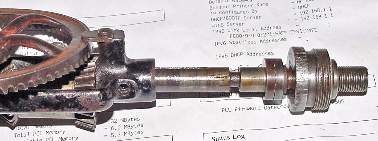
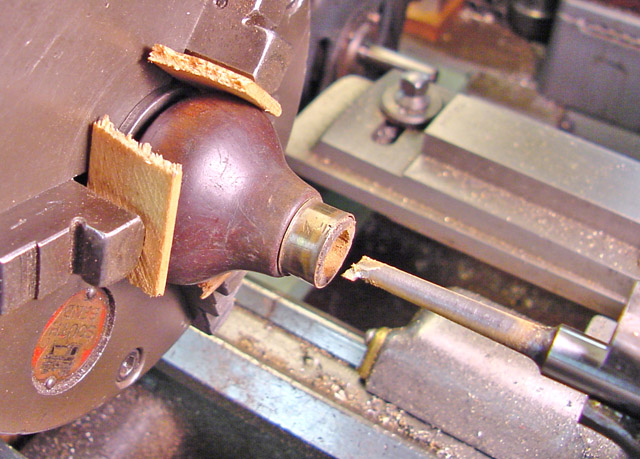
By removing the spindle from the frame, I could place it between centers.
|
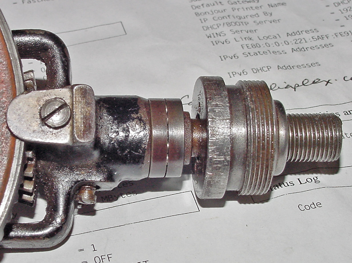
After some persuading, the thrust bearing came unstuck.
|
The first task was to clean up the end-most one or two threads which
had been distorted by a previous owner's operation of the chuck
without a key part. Placing the spindle between centers allowed
me to use a triangular file and a single point tool (a lathe threading
tool) as a scraper to remove the distortion without affecting the appearance of the
threads.
|
|
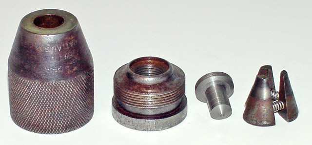
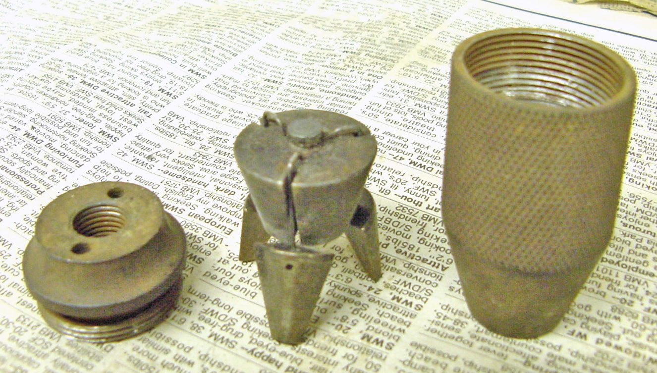
The base of the chuck contains an element that
presses against the bottoms of the jaws when the shell of the chuck is
screwed tighter onto the spindle. The hollowed-out end of the
spindle presses against the conical small end of the pushing element;
the small contact area minimizes the frictional torque between the
pusher and the spindle, so the chuck is self-tightening under load.
I also made a new set of springs as described above. The springs
have to be a close fit inside the holes in the jaws, and the wire
diameter should be large enough to generate sufficient force to make
the jaws spread out inside the shell, and yet not become coil-bound
when fully tightened.
|
The knob that was on this drill had been adapted from another drill's
side knob and was most insecurely attached. I pulled out its
threaded shaft and bored out the knob for a wooden sleeve, then made a
new shaft from a handy 5/16-24 Allen head, stainless steel cap
screw. The new shaft is held onto the crank by a nut which I cut
into two parts in the ratio 1/3 - 2/3. The thinner part became the
outside lock nut and the thicker part became a threaded sleeve to fit
inside the bored-out knob (3/8 inch inside diameter). In the
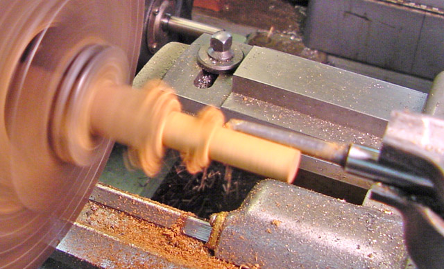
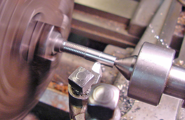
image at far right, I am turning down the shortened cap screw to fit
the 0.205 inch hole inside the mahogany sleeve. The round-nose
turning tool left a generous radius at the junction between the shaft
and its (still) threaded base. I am taking light cuts because the
jam nut and threded sleeve can't be very tight - they're all that are
driving the shaft for the turning operation.
|
|
|
|
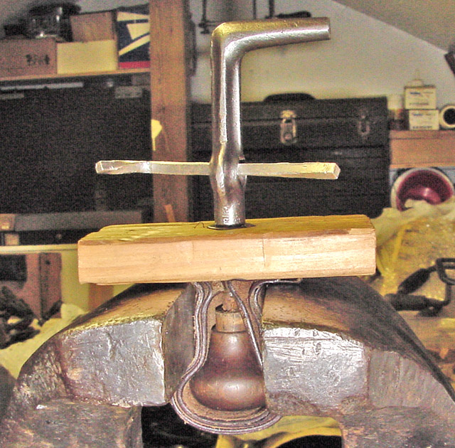
The old belt protected the knob.
|
Three equally thick pieces of soft wood ...
|
Scrap Honduras mahogany became the sleeve.
|
Turning down the shaft to 0.203 inch.
|
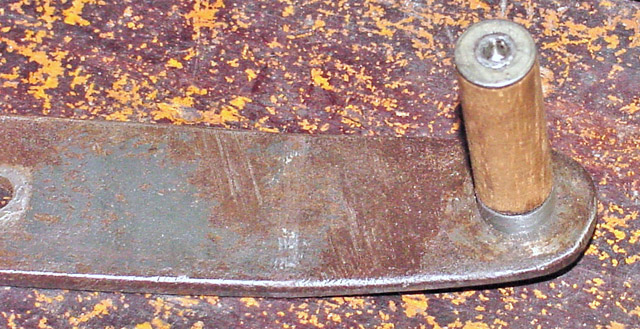
Now the next part is serious: This is the method used to attach the
pads to old braces - it's permanent, because the sleeve is glued inside
the knob.
The washer was peened tightly to the reduced-diameter end of the shaft,
so the bearing surfaces are the opposite ends of the mahogany sleeve.
|
|
|
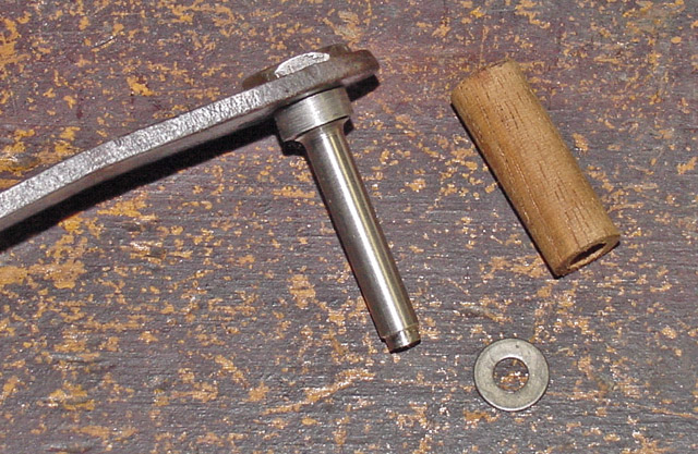
The
threaded sleeve is used to adjust the end play of the mahogany
sleeve on the shaft after the washer is peened onto the shaft to hold
the sleeve in place.
|
Here's
the assembly before I glued the knob on. Thankfully, I thought to
put a couple of drops of oil inside the knob - carefully, so as not to
spoil the gluing process. I bent the crank plate to improve one's wrist angle.
|
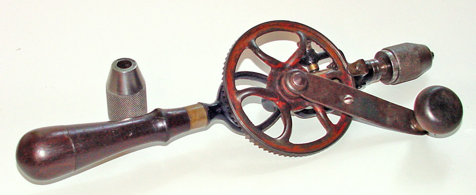
The
drill is now all back together with a free-running ball thrust bearing
and a smoothly turning knob ... while not the original crank and knob,
its just as useful.
|
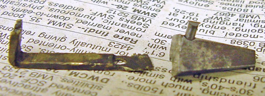
The replacement jaw retainer was potentially a nightmare - if I had
tried to make it by bending sheet steel to shape - it wouldn't tolerate
repeated adjustments/bends. My solution was to carve the retainer
out of the solid metal, as it's not called upon to deflect or to resist
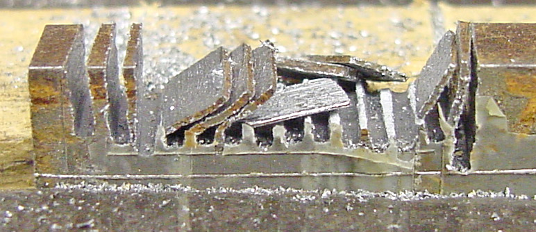
much force. The saw cuts greatly sped up the shaping
process. Note how delicate its attachment to the jaw is !
|
|
|
|
|
The original chuck had a poorly fitted jaw.
|
The peened-in pin was hard to get out.
|
All together now !
|
Lots of space for the retainer ends.
|
The jaw tips don't match.
|
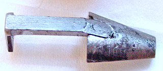
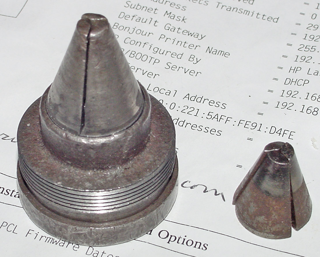
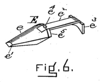
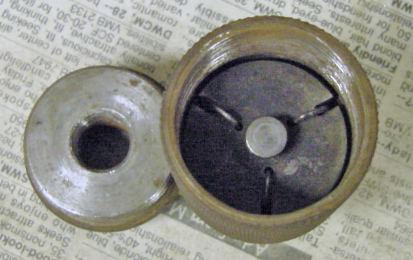
Whoa ! It turns out that there are two protected-springs designs
of the Millers Falls chuck. They are not interchangable, as the
truncated cone that aligns the springs in the original patent has a
pointed tip, a lot like the Goodell-Pratt chuck described above.
The alternative design has a smaller, cylindrical extension to fit
against the drill spindle. The original patent shows a third way
... The protected-springs chucks that have the patent date
imprinted in them are all the coil-spring, original design. None
of the chucks with the S-shaped springs has any markings, even though
they were used exclusively on Millers Falls drills. These are the
size used on the No.2 eggbeater drills with either the LRRCW, two
pinions, or both two pinions and the LRRCW.
|
|
|
|
U.S. Patent 660,121, issued October 23, 1900.
|
Archie's jaw design in the patent.
|
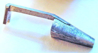
An unmarked Millers Falls chuck with S-springs.
|
The connection to the spindle is different !
|
|