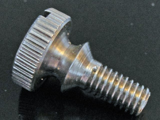
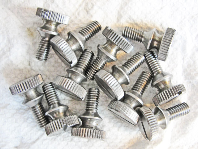
Here's my first one, warts & all.
|
The
original thumbscrews all have diamond-pattern knurling, so I made mine
with straight knurls. The screw slot is extra wide, because that was
dictated by the available slotting cutter. All the rest were too
thin ...
The wasp waist makes it an easy matter to capture the screw with a wire
or string to tether it to the nearest spoke of the main gear, a feature
never seen in the wild.
All my screws were made by chasing with a single point tool, as attested
by the "stop" position of the thread at the bottom of the countersink
bevel. Only thread milling could approximate such a complete
thread. The tapped threads in the main gear's spoke has no
countersink, so it is essential that the threads reach at least this
far, lest they interfere with the threads in the main gear wheel.
|
|
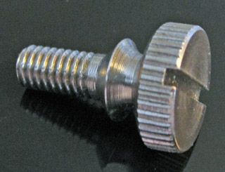
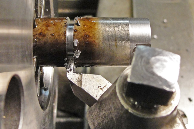
Although
I changed the order of my machining steps during the course of the
project, here's the earliest stage of the first screw, with a pass to
establish the head diameter and then a second cut to establish the
overall length of the screw and guide the cutoff (done last with a
hacksaw).
Later on I settled on the following
sequence: Turn an inch of the bar down to the diameter of the screw head
(0.512 inch); turn 0.38 inch of the bar to the screw-body diameter
(0.205 inch); bevel the end of the screw body; plunge cut the waist to
0.235 inch minimum diameter; finish the countersink head diameter to
0.38 inch; thread the screw body to 28 threads per inch, 0.187 inch
pitch diameter (+0, -0.002 inch); plunge cut the head to a thickness 0f
0.15 inch, about 0.12 deep; knurl the head; part off with hacksaw;
reverse the screw in the headstock and finish face off the top of the
head, leaving a small pip in the center; plunge cut the 0.05 inch slot
in the Atlas mill; and wire brush in the drill press to remove burs.
|
|
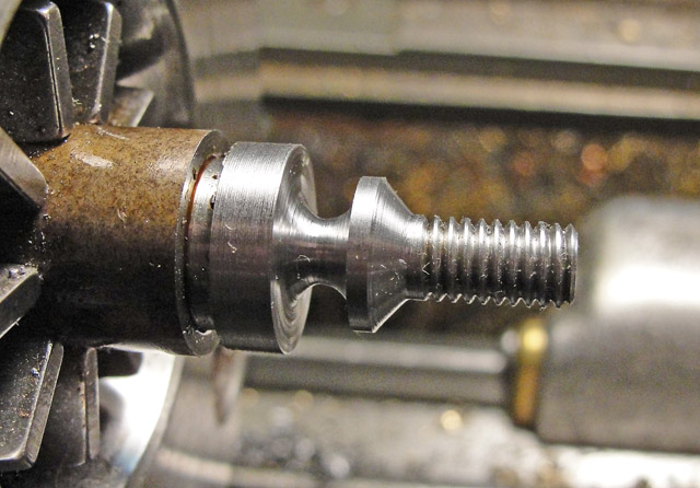
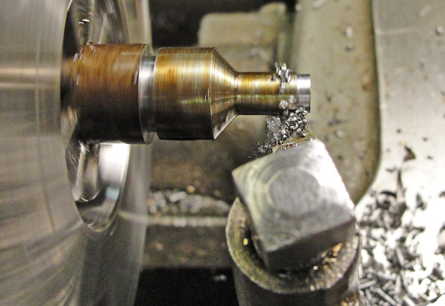
The
cutting tool has a small tip radius to blend the bevel into the body,
and it is set at 45 degrees to the screw axis to produce a 90 degree
countersink. After this cut, be sure to bevel the tip of the screw
to blend the start of the thread into the body, which makes starting
the screw into the tapped hole much easier.
I'm using sulfonated cutting oil which is meant for threading pipes. Smelly but effective.
The chuck is a Jacobs Rubber-Flex, bought new in 1960. Holds from 0.1
inch to 1.1 inch, but the South Bend lathe only passes 0.75 inch through
the spindle bore.
|
|
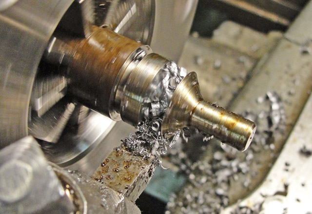
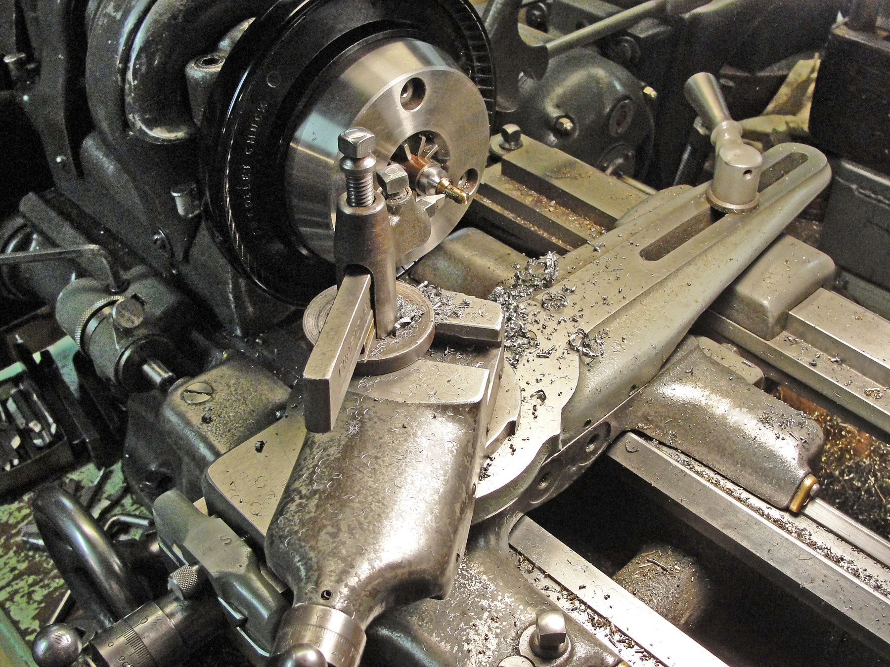
The
form tool used here is sized to shape the entire waist of the screw
without any need for lengthwise feed. It is important that there
be relief around the entire 180+ degree tip so there's no binding on the
sides of the cut. The tool chatters unless the spindle speed is
fairly slow, i.e., in back gear. Note that I remembered to bevel
the end of the screw body.
|
|
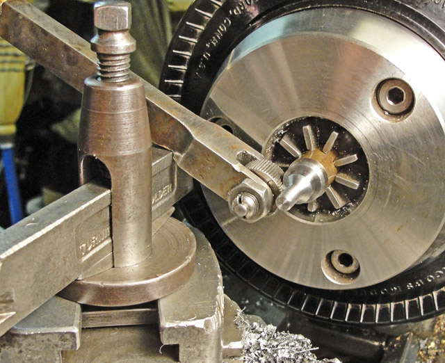
Here's
my threading setup. I learned hand scraping and tool alignment by
installing the taper attachment seen here. The micrometer stop
seen at lower left wasn't used for threading, but did come in handy for
machining the head diameter and the screw body diameter to length.
Not seen at bottom right is the threading dial, which is essential for
efficient thread cutting, as it eliminates
having to reverse the lathe to reposition the cutting tool. Be
sure to set the compound rest at 29 degrees off the perpendicular to get
a smooth finish on the screw threads; the main chip comes from the
front side of the cutter, while the back side just shaves the flank that
bears on the female threads when the screw is tightened.
|
|
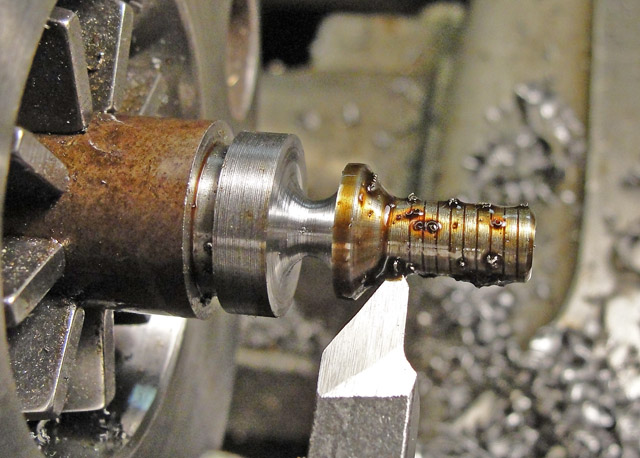
Here's
my first threading pass. Even with the relatively slim waist, the screw
did not visibly deflect during threading, as each successive cut
removes rather little metal.
It takes about six to ten passes to finish the screw to fit the tapped
hole in the main gear. Later on, I found my screw-thread
micrometer and finished all the next ten screws to a pitch diameter
within about +0, -0.002 inch. Below: threading done.
|
|
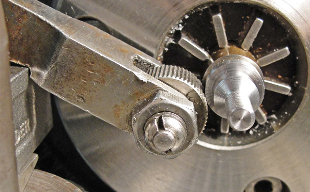
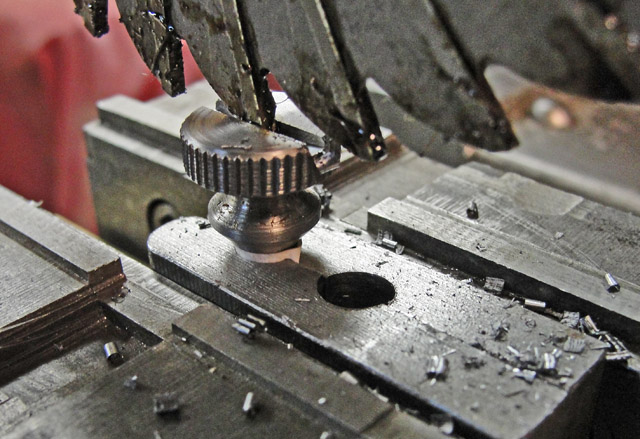
The
knurling tool came to me from tailgating at CRAFTS of NJ and puzzled me
until I noticed the notch on the bottom, about an inch-and-a-quarter
from the axis of the serrated cutter. That notch is to be
positioned on top of a firmly fixed fulcrum (a reversed tool holder set
parallel to the lathe axis) and the handle (not seen at upper left in
the picture at left) must be pulled down so the cutter comes up from below
the workpiece axis with the workpiece rotating normally. This causes
the leverage to increase as the cutter axis approaches a line drawn
between the workpiece axis and the fulcrum position. If you try
this backwards, coming down through center, the setup becomes unstable
and the cutter roll will snap through that imaginary line, damaging
something; I didn't do that !
|
|
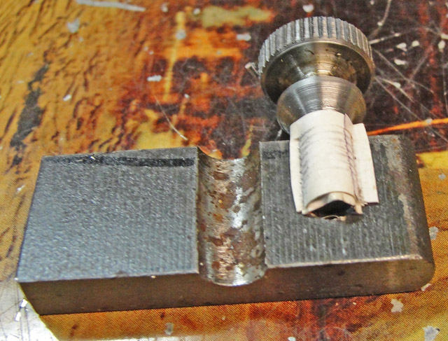
I
modified the workholder that I had used to finish the LRRCW mod's
discussed above by drilling a hole slightly larger than the screw body
down into the pair of bars and then wrapping a strip of paper around the
screw. When I didn't tighten the vise sufficiently, the milling cutter
simply slid the workholder out of the vise to the right. I left a pip in
the center of each semi-finished screw so I could sight on it to center
the screw underneath the cutter. I fed the knee of the Atlas mill
upwards to make the slot deeper in the center.
The slot really isn't needed, as it's easy to make the screw plenty tight with bare fingers.
Here's the screw holder taken apart.
|
|
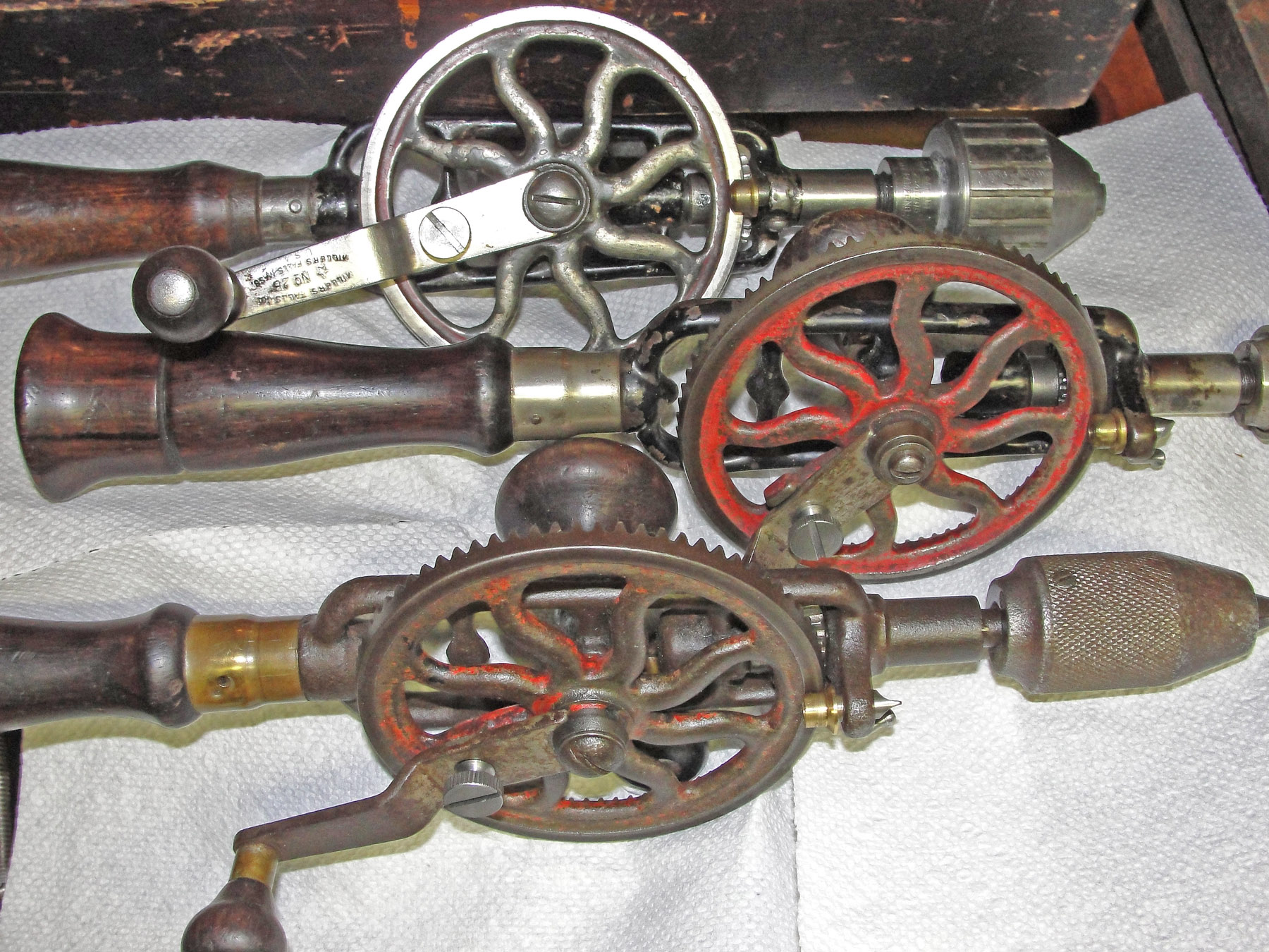
Here's a group of Millers Falls No.2 drills with modified LRRCW's and their new straight-knurled take-down screws.
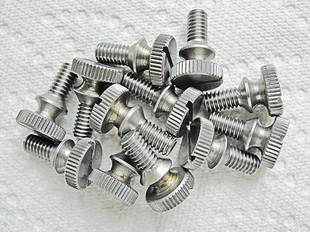
Below: all in a day's work (these are the large, 0.187-28 screws):
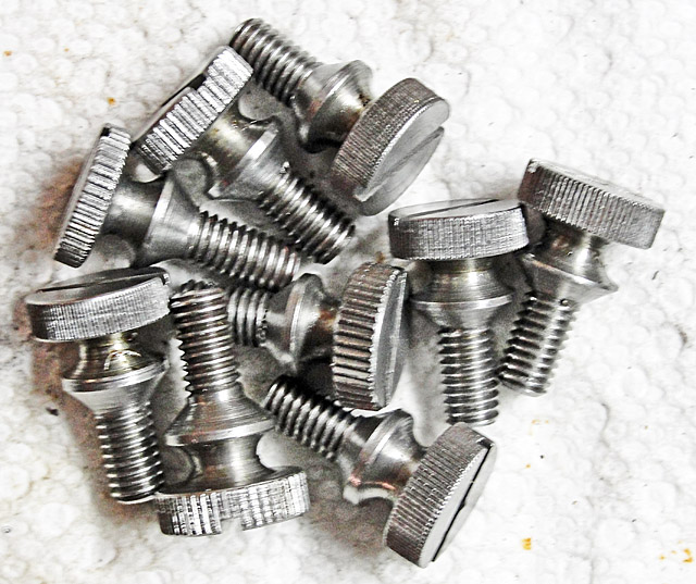
Some of the screws ended up with
with fine reeding and some with coarse. I'm new at this knurling
process, but I figured it out anyway ... Make the diameter a fixed
quantity (I used 0.512 inch) and apply heavy pressure with the spindle
in back gear; that forces deep enough marks that they catch the teeth of
the knurling roller on subsequent rotations.
|
|
However, on further investigation, I discovered that I had picked the only three drills (above)
that have large diameter tapped holes; others used smaller screws, with a
pitch diameter of 0.178 inch instead of 0.187 inch; and a third group,
usually the two-pinion drills, have coarser threads, 0.188 inch and 24
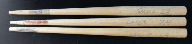
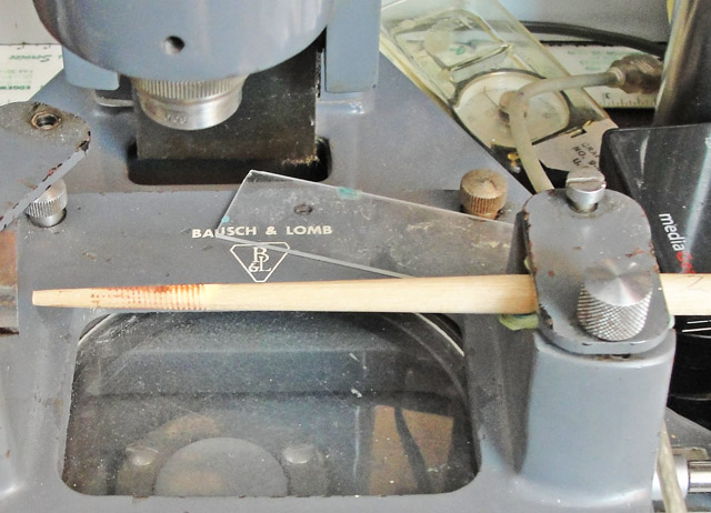
threads per inch. Therefore, some means for remotely sizing the
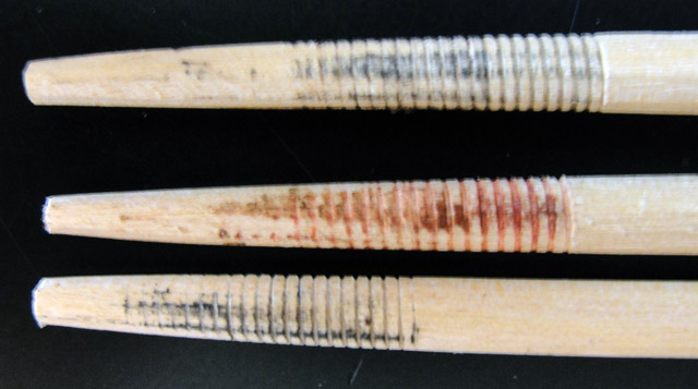
tapped holes in other No.2 drills became necessary. I chose the method
shown at left: 5/16 inch hardwood dowels tapered down to about 0.1 inch
at the small end over a distance of about four or five inches.
The dowels are: 0.178 - 28 at the top, 0.187-24 in the middle, 0.187-28 at the bottom.
|
|
|

|
|
Above: 0.178-28 dowel.
|
Above: 0.187-24 dowel.
|
|
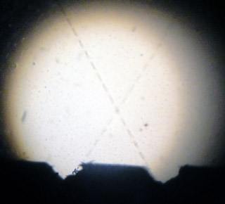
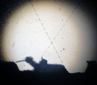
It
would be next to impossible for every user to make a perfect silicone
rubber replica of the inside of the tapped threads in his No.2
drill. The toolmaker's microscope and its specialized eyepiece
provide the solution: The adjustable crosshairs in the eyepiece can be
aligned so that the microscope measures the pitch diameter of the imperfect threads embossed into the wooden dowel.
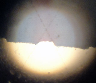
In the upper pictures at left the crosshairs outline a perfect 60
degree thread form and are positioned over what little of the imperfect
wooden replica thread exists; in the lower pictures, the same crosshairs
outline the 60 degree groove between adjacent threads.
The distance between the upper and lower positions of the dowel on the
microscope stage is the pitch diameter of the thread; and the
left-to-right distance between adjacent threads (male or female) is the
thread pitch, i.e., the reciprocal of the number of threads per inch, which are not counted like saw teeth, by the way.
The left-to-right position of the stage need not be adjusted during the
process of measuring the pitch diameter, because each thread is
diametrically opposite each groove.
Here's what the setup looks like in the toolmaker's microscope:
|
Dowel
|
Large-28
|
Small-28
|
Large-24
|
Measurement 1, inches
|
0.4629
0.2663
0.1966
|
0.4749
0.2847
0.1902 |
0.4670
0.2717
0.1953
|
| Measurement 2, inches |
0.4623
0.2670
0.1953
|
0.4748
0.2845
0.1903 |
0.4667
0.2721
0.1946
|
| Measurement 3, inches |
0.4619
0.2681
0.1938
|
0.4720
0.2848
0.1872 |
0.4673
0.2735
0.1938
|
| Measurement 4, inches |
0.4612
0.2693
0.1919
|
0.4720
0.2861
0.1859 |
0.4657
0.2720
0.1937
|
Average Pitch Diameter
|
0.1944
|
0.1884
|
0.1944
|
|
Here
are my actual measurements of the three tapered dowels after screwing
them each just once into the appropriate specimen drills' main
gears.
The difference in pitch diameter between the large-28 and small-28
dowels explains how I could end up with two classes of knurled screws -
the large-28 screw holes represent an extreme in the variability of the
diameters of the tapped holes, and the small-28 screw holes are just
enough smaller that they cannot accept my first batch of knurled screws,
which are 0.002 inch smaller to 0.001 inch larger than the holes they
would have had to fit inside.
The measurements of the two 28 threads-per-inch dowels also give me some
confidence about the sizes of the batch of 24 thread-per-inch knurled
screws which I intend to make next and about how I can fit new screws to
threaded holes which are thousands of miles away and out of reach of any kind of commercial go/no-go thread gauge.
The Large-24 screw thread turns out to be a No.12-24 and the large-28 might be close to the No.12-28 size; compare to these standards.
|
|
The screws at left are the small, 0.178-28 size. Below: 0.187-24 threads.
These are now for sale at $12 each with free shipping to the lower 48; please include your 5/16 inch dowel that you have made as described above so that I can pick the correct size screw to send.
I made my dowels with a block plane, which took about five minutes per dowel; there's no need to make yours perfectly round. |
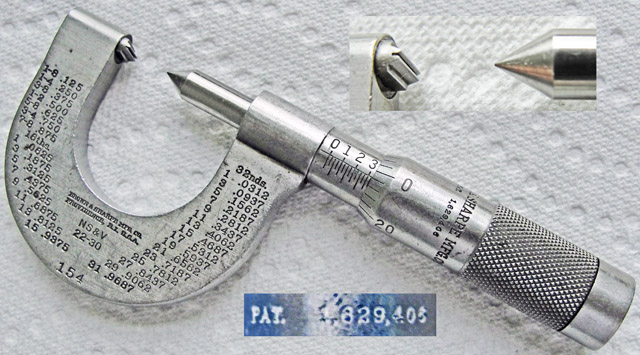
Brown & Sharpe thread-measuring micrometer for 22 to 30 threads per inch.
The patent (1,629,406) is for a method of adjusting the thimble.
Nevertheless, when the point is brought into contact with the vee, the
thimble reads zero, meaning that this micrometer measures the pitch
diameter of the threads. It would not have been practical for me to try
to make these screws with the alternative, three-wire method, which is
far more tedious.
|
|