|
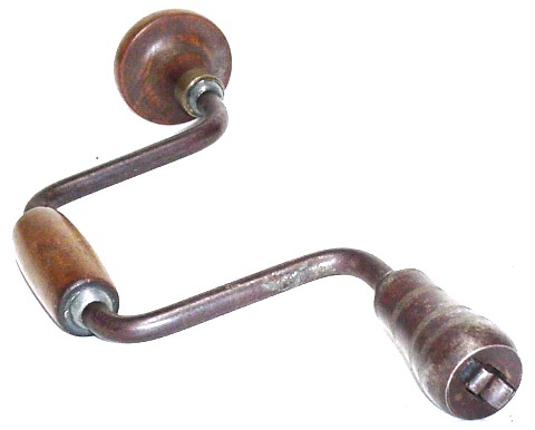
Whatever patent dates might have been marked on
the chuck shell of this brace have been obliterated by wrench marks,
but the patented features are utterly distinctive of two Backus
patents: U.S. Patent No. 234,517 (November 16, 1880) for the ratchet
selector mechanism and U.S. Patent No.250,047 (November 29, 1881) for
the chuck's jaws and their retention mechanism.
 There
was an issue with this brace's ratchet selector, as the pin connecting
to the selector sleeve was gone. I made the one you see here by trial
& error, as the screw size is midway between a No.8 and a No.10
U.S. Standard fine-thread machine screw. The patent isn't much help, as
there's no clue how the pin is retained. I found that the number of
threads per inch is 32, as a No.8-32 screw would go in, albeit way too
loosely to be of any other use. I simply turned the OD of my new pin a
little bigger than a No.8 screw, started chasing threads, and kept on
trial fitting the screw until it actually fit. I was lucky (or
sufficiently sharp-eyed) to get the 1/4 inch CRS steel bar back into
the collet in the right relationship to the chasing tool after every
trial fit. My loupe helped a lot. There
was an issue with this brace's ratchet selector, as the pin connecting
to the selector sleeve was gone. I made the one you see here by trial
& error, as the screw size is midway between a No.8 and a No.10
U.S. Standard fine-thread machine screw. The patent isn't much help, as
there's no clue how the pin is retained. I found that the number of
threads per inch is 32, as a No.8-32 screw would go in, albeit way too
loosely to be of any other use. I simply turned the OD of my new pin a
little bigger than a No.8 screw, started chasing threads, and kept on
trial fitting the screw until it actually fit. I was lucky (or
sufficiently sharp-eyed) to get the 1/4 inch CRS steel bar back into
the collet in the right relationship to the chasing tool after every
trial fit. My loupe helped a lot.
|

|
Here's the missing Fig.2 from my capture of page 1 of the Quimby patent:


My finished selector pin.
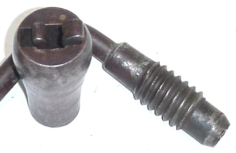
Here is the other patented feature of this brace, the jaw retention mechanism of U.S. Patent No.234,517:
 The
jaws are only meant to center the cylindrical part of the drill bit;
the square shank of the bit fits into a square hole in the socket of
the chuck and does the driving. Nevertheless, this pair of jaws
survived all the wrench insults that the chuck shell received. I have
seen a number of examples of this mechanism, but in the others the
copper-plated flat springs have usually been rusted away. The
jaws are only meant to center the cylindrical part of the drill bit;
the square shank of the bit fits into a square hole in the socket of
the chuck and does the driving. Nevertheless, this pair of jaws
survived all the wrench insults that the chuck shell received. I have
seen a number of examples of this mechanism, but in the others the
copper-plated flat springs have usually been rusted away.
|

|
I've
rearranged the elements of Mr. Quimby's U.S. Patent No.234,517 drawing,
the better to fit the present format. The actual brace follows the
drawing very closely, the principal difference being that the springs
are retained with machine screws, not just the single rivet which would
have been awkward to detach for replacement of a broken spring.
The attorney's signature is more legible here: J.C. Tasker, but it's a
different person than on the No.132,791 patent. Again, the witnesses to
the patent text signature (Frank B. Spalter and G.S. Loud) differ from
the witnesses to the patent drawing itself (F.H. Schott and W.E.
Chaffee).
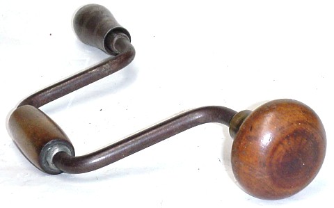
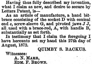
The pads of both braces turn stiffly at first but then free up
pleasantly once the brace is put into use and an oil film spreads over
the inside of the hole. They are apparently of the same design - and
quite difficult to disassemble, as I think the retention mechanism is
permanently glued in place and inaccessible from the outside. One oils
them only from the outside, simply by placing the lubricant along the
very tight fit between the wood and the frame ... followed by lots of
elbow grease to distribute the oil.
In the 250,047 patent, the drawing witnesses are John H. Stout and C.J.
Munn, but the text signatures are those of the same two men. There was
apparently no attorney of record for this patent, in contrast to the
earlier patent shown at left.
|


|
Here are the rest of the two Quimby S. Backus patents, 234,517 on the left and 250,047 below.
Note that the essence and enforceable legal portion of each patent is the Claims section at the very end of each patent's text.
Randy Roeder (a librarian by profession) has published a fine biography of Quimby S. Backus,
including his various businesses and his legal battles with the owners
of other patents which he was found to have infringed. His losses in
the legal arena simply spurred Quimby Backus to even greater
inventiveness so as to maintain a stock of defensible patent designs in
the braces that he made. The second brace on this page was backus's
finest hour in Mr. Roeder's estimation.
|
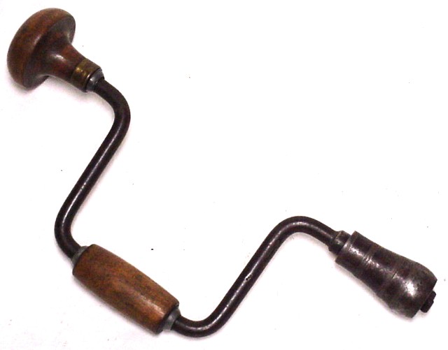
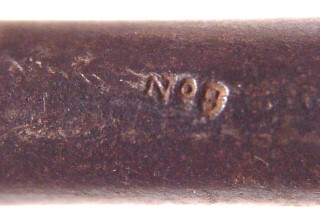
 The makers
mark on the chuck is quite indistinct, so I boosted contrast and
brightness, converted to greyscale, and then inverted to a negative
image. It is now possible to see the Nov. 5, 1872 date as well as
the Holyoke, Mass. company location.
The makers
mark on the chuck is quite indistinct, so I boosted contrast and
brightness, converted to greyscale, and then inverted to a negative
image. It is now possible to see the Nov. 5, 1872 date as well as
the Holyoke, Mass. company location.