Geared braces of which I have knowledge.
by George Langford, Sc.D.
Return
to georgesbasement
1. Bennett & Bloedel patent brace drills intended
for use not only as common bit braces but also as compact corner braces
for drilling holes in confined spaces (click on each image to see
aditional
design details).
a. Specimen 1.
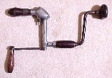 This
Bennett & Bloedel patent brace drill was made by E.C.Atkins &
Company,
otherwise famous for saws. The patent date is October 10, 1905.
A
nearly identical version of this design was seen at the recent PATINA
tailgating,
but that one was made by a different manufacturer.
This
Bennett & Bloedel patent brace drill was made by E.C.Atkins &
Company,
otherwise famous for saws. The patent date is October 10, 1905.
A
nearly identical version of this design was seen at the recent PATINA
tailgating,
but that one was made by a different manufacturer.
b. Catalog illustration corresponding closely to
the above Atkins specimen1(a).
 The
crank on my specimen is slightly shorter than the one illustrated here
in the 1914 catalog, so it interferes with the crank handle of the
brace.
The gears are not only totally enclosed in this design, but they
also permit the crank gear to ratchet. Two different chuck
designs
were offered by Atkins; the specimen in 1(a) has the "other"
kind. The crank is held onto the gear shaft with an elegant
captive
key that engages a small groove in the end of the gear shaft.
The
crank on my specimen is slightly shorter than the one illustrated here
in the 1914 catalog, so it interferes with the crank handle of the
brace.
The gears are not only totally enclosed in this design, but they
also permit the crank gear to ratchet. Two different chuck
designs
were offered by Atkins; the specimen in 1(a) has the "other"
kind. The crank is held onto the gear shaft with an elegant
captive
key that engages a small groove in the end of the gear shaft.
c. Catalog photograph of a specimen made by Lancaster
Machine & Knife Works, Lancaster, New York.
 The
photograph was included with Specimen 1(a) as provenance, but it is not
the same drill. The crank arm of the Lancaster drill is a
casting,
and the crank arm of Specimen 1(a) is rectangular section wrought steel.
The
photograph was included with Specimen 1(a) as provenance, but it is not
the same drill. The crank arm of the Lancaster drill is a
casting,
and the crank arm of Specimen 1(a) is rectangular section wrought steel.
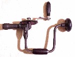
2. Several Millers Falls brace drills.
These geared braces are all impossible to use close to an inside
corner because the axis of the large gear is immutably parallel to the
torque arms of the brace crank (click on each image to see aditional
design
details). The apparent purpose of their geared drives is to turn small
bits more quickly than can be done with the plain double crank of the
brace.
That interpretation is supported by the catalog illustration
found
for the third geared brace in this series, No.2(c) below. The
first
two braces function well, although their delicate construction hints
that
their gear sets are intended only for light duty. It would not
make
sense to struggle with a 1:3 mechanical disadvantage to turn the geared
crank when the double crank of the brace has the direct 1:1 ratio.
The
first two braces are presented in their apparent chronological order.
The
third brace has not been dated and might not have been made by Millers
Falls, although that maker's name appears on the chuck shell. The
identical text goes with illustrations of the second and third braces
in
two different catalogs, and the sketch of Brace Drill No. 2(b) matches
that in the Millers Falls catalogs that I have, so that supports the
notion
that Millers Falls did actualy make the cruder Brace Drill No.2(c).
The
design of the complex Brace Drill No.2(d) allows for various
orientations
of the axis of rotation of the main gear, but still does not permit the
drill to work close to a corner.
Quickly
compare the overall arrangements of the top three braces
a. Patent date March 23, 1880 (Brace Drill No.1)
 Gear
and crank are held on by a winged nut that fits in the end of the gear
shaft.
Gear
and crank are held on by a winged nut that fits in the end of the gear
shaft.
b. Same design, later crank (Brace Drill No.2)
without
patent date.
 Similar
to Brace Drill No.1, but the nut is knurled instead of winged.
Similar
to Brace Drill No.1, but the nut is knurled instead of winged.
c. Cruder design, unknown date (Brace Drill No.3).
 The
least successful design of the three on this page, this geared brace
comes
with a winged screw that fastens the entire gear, crank and gear shaft
to the elbow of the brace. The winged screw has a conical tip
that
serves to force the two ratchet pawls to disengage from the ratchet
wheel.
This feature prevents the frustrating occurrence of leaving the
ratchet
engaged, which can prevent the crank from being turned. None of
these
three drills' gear drives can ratchet; that function applies only to
the
brace mechanism. The attachment of the gear to this brace is not
rigid enough to keep the gear in mesh with the pinion, so the teeth
slip.
Brace Drills No.'s 1 & 2 do not have this fault, because
their
gear shaft housings are integral parts of the brace housing.
There
is a drawing of this brace drill in the trade catalog #21 of Montgomery
& Co. but there is no copyright date in that catalog and no maker's
name for the drill. In that catalog this is termed a "drill
brace." The catalog illustration for Brace Drill No.2 has the identical
text as the catalog illustration for this version, Brace Drill No.3,
but
was published in 1922; it would appear that this cruder design
antedates
the designs of Brace Drills No.'s 1 & 2.
The
least successful design of the three on this page, this geared brace
comes
with a winged screw that fastens the entire gear, crank and gear shaft
to the elbow of the brace. The winged screw has a conical tip
that
serves to force the two ratchet pawls to disengage from the ratchet
wheel.
This feature prevents the frustrating occurrence of leaving the
ratchet
engaged, which can prevent the crank from being turned. None of
these
three drills' gear drives can ratchet; that function applies only to
the
brace mechanism. The attachment of the gear to this brace is not
rigid enough to keep the gear in mesh with the pinion, so the teeth
slip.
Brace Drills No.'s 1 & 2 do not have this fault, because
their
gear shaft housings are integral parts of the brace housing.
There
is a drawing of this brace drill in the trade catalog #21 of Montgomery
& Co. but there is no copyright date in that catalog and no maker's
name for the drill. In that catalog this is termed a "drill
brace." The catalog illustration for Brace Drill No.2 has the identical
text as the catalog illustration for this version, Brace Drill No.3,
but
was published in 1922; it would appear that this cruder design
antedates
the designs of Brace Drills No.'s 1 & 2.
d. An attempt at a more versatile design (Brace Drill
No.4).
 Remember
that I said that none of the above three Millers Falls braces would
work
close to corners ? Well, do not be fooled by the ability of this
even more complex Millers Falls brace (which I have never seen in the
wild)
to be assembled with the main gear's axis in any one of three
orientations.
It still won't work in a corner like the Bennett & Bloedel
patent
brace drills at the top of this page. It was found as Model 192
in
the 1915 Millers Falls Catalog No.35 (reprinted by Roger K. Smith), but
it is already absent in my original 1925 Millers Falls Catalog No.33.
Remember
that I said that none of the above three Millers Falls braces would
work
close to corners ? Well, do not be fooled by the ability of this
even more complex Millers Falls brace (which I have never seen in the
wild)
to be assembled with the main gear's axis in any one of three
orientations.
It still won't work in a corner like the Bennett & Bloedel
patent
brace drills at the top of this page. It was found as Model 192
in
the 1915 Millers Falls Catalog No.35 (reprinted by Roger K. Smith), but
it is already absent in my original 1925 Millers Falls Catalog No.33.
3. An elaborate spur-geared breast drill which also functions like a
brace.
a. Ephemera included with a salesman's sample.
 This
booklet was included with the following Ultra-Rapid spur-geared breast
drill. It was clearly translated from another language (probably
German) into English, so it takes some interpretation to decipher the
extravagant claims. The booklet announces that the tool is
intended for the "Sole distribution for Argentine, Brazil, and
Phillippine Islands by Europa-Transocean Warenhandels-Compagnie m.b.H.
This
booklet was included with the following Ultra-Rapid spur-geared breast
drill. It was clearly translated from another language (probably
German) into English, so it takes some interpretation to decipher the
extravagant claims. The booklet announces that the tool is
intended for the "Sole distribution for Argentine, Brazil, and
Phillippine Islands by Europa-Transocean Warenhandels-Compagnie m.b.H.
Berlin W 50 (Germany), Neue Bayreuther Strasse 2." The spindle has ball
bearings, and the gears are all straight-cut spur gears, so in "effect
the drilling-speed of „Ultra-Rapid" is the double of that of an
electric Hand-Drilling-Machine or seven times more as that of the best
so-called American Hand-Drilling-Machine. This special speed is
attained by the accurate constructional workmanship and by the enormous
oscillating-power of the driver. In experimentalizing to drill we
had the following result, where all 3 machines were working with 5 mm
spiral drill in 6,5 mm angle-iron and for a time of 3 1/2 minutes real
drilling and without marking any center ..."
Sure. When I try this drill, the low speed is about 1:1 turn
of the drill bit to a turn of the crank, making this a
flywheel-assisted geared brace. The high speed is about 5:1,
making this speed about the same as one of Goodell-Pratt's high speed
hand drills.
b. The Ultra-Rapid drill itself.
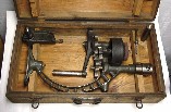 The
Ultra-Rapid spur-geared breast drill was perhaps the inspiration for
OSHA, the Occupational Health & Safety Administration.
Ultra-vigilant usage of this tool is an absolute requirement, as the
geared flywheel keeps the drill's gears revolving with great force for
some fifteen seconds after one lets go of the handle. The breast
plate is imprinted with the Ultra-Rapid trade name and "Made in
Germany," making this a pre-WWII model, post-1900, more-or less.
It may be that the flywheel's impressive amount of stored kinetic
energy allows the user to apply more force in the "easy" portion of a
rotation and to coast during the "hard" portion.
The
Ultra-Rapid spur-geared breast drill was perhaps the inspiration for
OSHA, the Occupational Health & Safety Administration.
Ultra-vigilant usage of this tool is an absolute requirement, as the
geared flywheel keeps the drill's gears revolving with great force for
some fifteen seconds after one lets go of the handle. The breast
plate is imprinted with the Ultra-Rapid trade name and "Made in
Germany," making this a pre-WWII model, post-1900, more-or less.
It may be that the flywheel's impressive amount of stored kinetic
energy allows the user to apply more force in the "easy" portion of a
rotation and to coast during the "hard" portion.
Return
to georgesbasement