Go back to Main Study Page
The Little Rail Road Car Wheel's Dimensions and Theory of Operation
 The
Millers Falls Types K through D all had
the
anti-friction gear support roller that I call the Little Rail Road Car
Wheel (LRRCW). I picked one of the later ones, a Type
D (made in Greenfield, Massachusetts and sporting lacquered
mahogany
main & crank handles and the smaller side handle that "belongs" to
the two-pinion types) because it remains relatively unused as evidenced
by the triangular Millers Falls logo decal on the main handle.
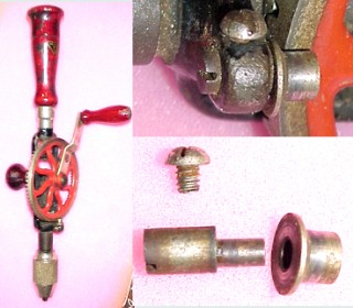
The three parts of the LRRCW assembly are the cam (at lower left in the lower right hand portion of the composite picture at left), the LRRCW (to the right of the cam), and a lowly round-headed No.6-32 clamping screw. The exploded parts are shown in the same orientations and relative positions as in the detail view above the picture of the individual parts, but the drill itself is shown rotated 90 degrees counterclockwaise from the detail view.
The LRRWC should be adjusted so that it just barely allows the main gear wheel to rotate without binding anywhere in the rotation of the gears. That is done by loosening the clamping screw and then rotating the cam with a second screwdriver. A purist would tell you to orient the cam so that the frictional drag of normal rotation of the main gear will tend to losen the fit of the LRRCW should the clamping screw lose its grip. Otherwise, just twist the cam back and forth while trying real hard not to push it in towards the rim of the main gear until everything is snug without binding. Then you can retighten the clamp screw.
The function of the LRRCW is to keep the main gear and single pinion gear in correct mesh along their corresponding pitch lines, thereby minimizing backlash and ensuring accurate, smooooth rotation under load. The LRRCW assembly is extremely stiff, so it does not perceptibly deflect under load. The shaft upon which the flanged roller (the LRRCW) rotates is quite small in diameter, so there is little friction when the assembly operates, even under load.
The LRRCW mechanism contrasts sharply with the conventional two-pinion method of supporting the main gear (used shamelessly in the later MF No.2 types) whose second pinion is the same size as the drive pinion but is not adjustable for clearance. The two-pinion arrangement depends on the stiffness of the relatively slim main gear for workable functioning, and the second pinion rolls no more efficiently than the drive pinion and a lot less efficiently than the smooth-surfaced LRRCW and its small-diameter shaft. Think about it some more and you might even justify deciding whether the cam should lead or lag based on the tendency of the flange of the LRRCW to either crowd against the main gear's outside diameter (not good) versus having the LRRCW slide back out of the way against the shoulder of the cam, where it belongs.
 Now
let's suppose you have acquired a nice MF No.2 w.LRRCW that doesn't
actually
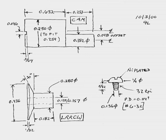
have its LRRCW any more. The drawing at left gives the important
dimensions
of the three parts. Make the cam of tool steel or drill rod and harden
it to about Rockwell C48. The LRRCW itself should be made from
cold-rolled
steel. Make the clamping screw by shortening a nickel-plated machine
screw
... which must be nickel plated; heh, heh. The other two parts appear
to
have some residual nickel plating also.
If you compare dimensions of the mating parts, you will see that Millers Falls left lots of clearance. For example, the cam's shaft extension is 0.152 inch in diameter, but the hole in the LRRCW is between 0.159 and 0.157 inch in diameter as measured with number-drill-sized plug gages. That's 0.005 to 0.007 inch clearance. Lots of room for fairly thick oil that won't leak out. The drilled hole in the frame of the drill has a measured diameter of 0.259 inch, and the outside diameter of the body of the cam is 0.250 inch, so there's nine mils of clearance there, which is OK because those parts only get rotated during the occasional adjustment of the LRRCW.