 |
The
Millers Falls Company developed the best single-speed, non-ratcheting,
eggbeater drill
there
ever was ... ... until Marketing vanquished Engineering. |
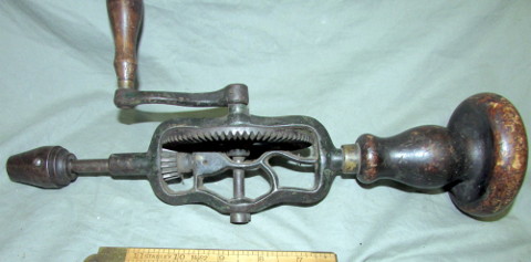 |
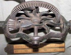
Just when we thought that all scientific discoveries had already been made, Sandy Moss came up with this find at a Spicer auction: The Type O No.2 drill. Its connection to the Millers Falls Company is circumstantial and consists only of the frame shape (but much more robust), the 1877-patent chuck and its threaded mounting on the spindle, and the numbers of teeth on the main gear (77) and single pinion (17). The gears are both solidly pinned to their shafts, and so is the crank. There is no lining on the periphery of the rather flat main gear, but the main handle is probably a replacement, judging from its sawed-off threaded shaft. | ||
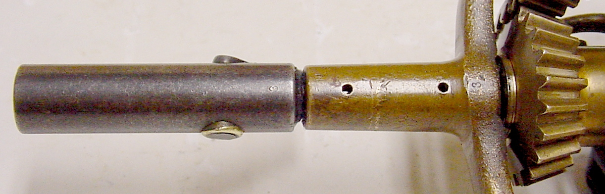 |
Right
about the time that Millers Falls redesigned the frame of the Type O
drill so it could be easily chill cast in preparation for the necessary
malleablizing heat treatment that made the frame both ductile and
machineable, a
small batch of bronze framed Type P drills and a larger
batch of cast iron Type M drills were made in their machine shop,
as indicated by
the match markings used in the hand fitting of key parts. The frame,
pinion, and spindle of the drill at left are all stamped "3". |
||
 |
At left are the earliest
types which appear in the oldest known Millers Falls catalogs. The
earliest
patent date I find on the chucks, for example, is August 14, 1877.
Their
wrap-around frames support the main gear wheel's shaft at both ends,
but
do not protect the brittle cast iron (or bronze) gear against
deflections
from the forces acting between the teeth of the mating gears. The
cast iron cranks occasionally bend but rarely break; however, they are
weakly pinned to the main gear's shaft. Watch for the flat face
of the earliest main gears and the lining on the earliest main
handles. The Type M is further distinguished by the sixteen teeth
of the pinion gear. Later models in this series have seventeen
teeth, a prime number, which improves the wear resistance of the teeth
of the two gears because individual pairs of teeth rarely meet.
The
evolution of the main handles of these types closely follow the
evolution of the main handles of the early No.1,
3 & 5 eggbeater drills also made by Millers Falls. The drill on the left is Type N, followed by Type M, Type L, and an untyped mongrel. |
||
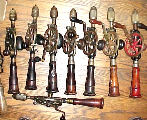 |
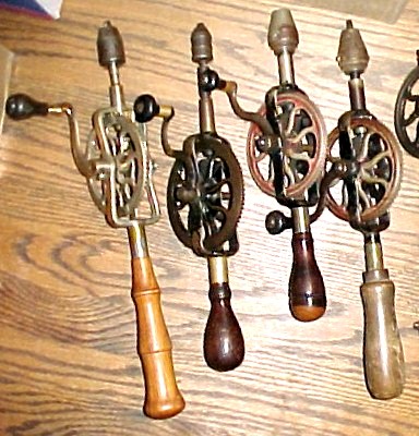
Next,
Millers Falls abruptly jumped to what I think is the best designed
eggbeater
drill ever. A modest little flanged roller was added, outboard of the
main
gear, which supports the thrust that tends to push the teeth out of
engagement.
Millers Falls called this the "adjustable friction roll to equalize
bearings"
and never showed it in any of their catalog images. No one ever copied
it; Goodell-Pratt tried to emulate the roller with their little
hardened
steel wiper, but that's as close as anyone came to adopting this
innovation. I
call it the "Little Rail Road Car Wheel" (LRRCW) model. The drill
arranged
crosswise in the picture at left is my first LRRCW drill, which I
rescued
as a box of bits of rusty metal and splinters of wood, which I later
pieced
together and polished. It's my sweetest running eggbeater drill. The
LRRCW
and some well-hidden ball bearings make this drill sing; it takes less
effort to operate than any other drill I use. The Type F (Star logo) and Type E (triangular Since 1868 logo) are the commonest types found. |
||
|
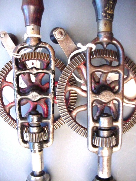
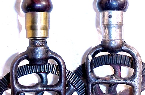
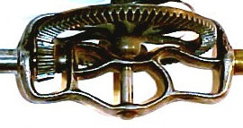
About the time that the Millers Falls
Company purchased the Goodell-Pratt Company and moved from Millers
Falls to Greenfield,
Massachusetts, someone tried out a method of adding a second pinion to
support the side thrust between the main gear and the pinion
gear. This was presumably in response to market pressure from
other manufacturers. It is difficult to justify the change, as it
almost certainly cost more to make and machine that second pinion than
the roller, its cam-shaft and the adjusting screw of the LRRCW.
The second pinion of this model was installed on an extension of the
threaded shaft of the main handle, and the frame had to be spot-faced
and threaded to accept the extra parts. I figured that this was a one-off prototype that some fortunate collector had stumbled upon or spirited away from an archival collection of the manufacturer. Not so fast, buster. Then I spotted another one in a different place. Millers Falls actually sold their research & development models - perhaps to test the market. Both examples of Type DC have the "Since 1868" triangular logo stamped on the crank. The very next Type D was made in Greenfield. One gets the impression that this was a last-gasp effort by a company being consumed ... not an improvement being developed by an energetic staff ... in spite of the fact that the record says that Goodell-Pratt was purchased by Millers Falls. |
||
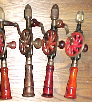 |
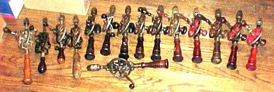
Last (and least, to my way of thinking) are the double-pinion No.2's, which Millers Falls started to make some time after moving their plant to Greenfield, Massachusetts, from Millers Falls. The LRRCW was eventually ditched, and Millers Falls went to what had become the standard way of keeping the gears in mesh. Never mind that it takes a lot more work to turn a pair of meshing gears than to spin a roller (especially when neither method is supposed to be delivering any work through the process) and that the second pinion does nothing to take the side load off the main gear; that's just what the competition was doing. To make matters worse yet, all the auction action today is with the last two types in the picture at right, and the brighter and uglier the orange handles, the higher the price. Go figure. |
| What were the main engineering
changes ? You
might ask ... |
|
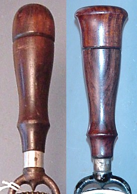
The frame of the Type O
drill (far left) is the most robust of any type of No.2 drill; compare
to the thinner & less massive frame of the Type Pre-L
drill to its right. As both drills were fitted with the
1877-patent-date two-jaw chuck whose maximum bit capacity is only
one-quarter inch, it must have seemed logical to make a more slender
frame. On the other hand, this metallurgist also notes that the
Type O's thick frame may have been too difficult to make as malleable
iron,
which demands rapid cooling of the liquid metal in the mold to achieve
the necessary metallurgical state of the raw casting. |
||
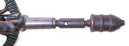 |
The Type M
drill has a tapered socket in the spindle. Earlier drills used a
straight hole and set screw like a post drill. It was also match-marked
during its manufacture in a batch of more than ten at a time in the
Millers falls machine shop while the firm was gearing up for later,
higher volume production. |
||
 |
This
is the two-jaw springless chuck patented
on August
14, 1877. The jaws each had a V groove in the middle, but the
opening between the jaw guides only permitted 1/4 inch bit shanks to
be gripped. The minimum bit size was about 1/16th inch, not a very wide
range compared to later three-jaw chucks the same outside diameter.
This
jaw design was also prone to losing the jaws, distorting the chuck
shell,
or breaking jaws because they hang out too far in order to grip the
smallest
bits in the range. It's better than that hollow-tapered spindle
above, though. |
||
 |
Type L2 on the left; the earlier Type L0 is on the right. The bits that the shorter handle was meant to accommodate were all the same length, but the later twist drill bits were made in what became known as jobbers lengths, meaning that the larger diameter bits were also longer, because they could drill deeper holes. The short, straight-flute bits had to be repeatedly withdrawn from the holes being drilled because they tended to clog with chips. |
||
 |
The three parts of the LRRCW assembly are the cam (at lower left in the lower right hand portion of the composite picture at left), the LRRCW (to the right of the cam), and a lowly round-headed No.6-32 clamping screw. The exploded parts are shown in the same orientations and relative positions as in the detail view above the picture of the individual parts, but the drill itself is shown rotated 90 degrees counterclockwise from the detail view. The LRRCW should be adjusted so that it just barely allows the main gear wheel to rotate without binding anywhere in the rotation of the gears. That is done by loosening the clamping screw and then rotating the cam with a second screwdriver. A purist would tell you to orient the cam so that the frictional drag of normal rotation of the main gear will tend to loosen the fit of the LRRCW should the clamping screw lose its grip. Otherwise, just twist the cam back and forth while trying real hard not to push it in towards the rim of the main gear until everything is snug without binding. Then you can retighten the clamp screw. The function of the LRRCW is to keep the main gear and single pinion gear in correct mesh along their corresponding pitch lines, thereby minimizing backlash and ensuring accurate, smoooooth rotation under load. The LRRCW assembly is extremely stiff, so it does not perceptibly deflect under load. The shaft upon which the flanged roller (the LRRCW) rotates is quite small in diameter, so there is little friction when the assembly operates, even under load. |
||
 |
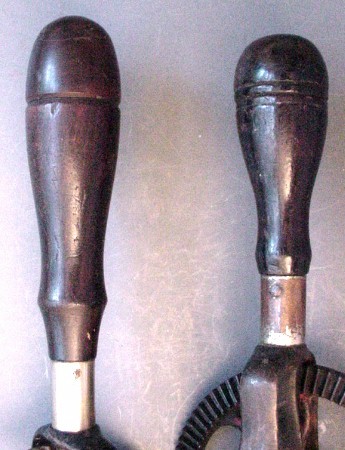
The crank handles of the Type M, Type Pre-L, Type L and the Type K2 are shown arranged left-to-right at left. Each of the first three cranks has a boss cast in to hold the axle of the rotating crank handle, but the Type M's handle is held with a screw carefully tapped into the crank (but loosened for the camera) the Type Pre-L's crank is held with a pin apparently press fit into that boss but whose head is peened over a washer to retain the rotating handle, and the Type L's crank handle is held by a large-headed pin riveted at the inboard side of the boss, which was drilled clear through to receive the pin. The crank handle of the Type K2 was held like that of Type L, but the crank of the Type K's and all later No.2 drills are thin steel, and so their crank handles are not so securely attached as these early three drills' handles. | ||
 |
On the left is the worn thrust bearing of the Type L2. On the right, it's the Type L0's thrust bearing, where someone has attempted to compensate for wear. The Type Pre-L had a little different arrangement for taking care of end thrust. The Type L uses a single, hardened steel ball to handle the thrust; perhaps this example of the Type L2 once did as well ... | ||
 |
The very first No.2 drill that used the LRRCW to control the running fit between the main gear and pinion gear had a very plain thrust bearing. That bearing supported the force of pressing the bit against the workpiece being drilled. The bearing was a simple cylinder whose position could be adjusted and held in place with a small screw visible here between the spokes of the main gear. That simple bearing was not easy to keep lubricated and had high friction compared to the efficient solution that appeared with the more heavily loaded Type K5 and later drills: a row of tiny steel balls between the upper end of the spindle and the inside of the spindle's bearing housing. | ||
 |
The
first LRRCW model of
the No.2 eggbeater drill did not just spring to life fully
developed.
Only the LRRCW achieved that feat of inspiration, never imitated since
in any hand drill that I've seen. The first frame, the Type K1's at right,
was
narrow and lacked any provision for a side handle. The next
model,
the Type K2 at left, had a wider frame,
presumably stronger. I
have
never come across a broken frame in a No.2 drill. These frames
were
made of malleable iron, a ductile, tough material in its time.
Later
frames were made of pot metal; they didn't break, either. Both of
the drills shown here have the cylindrical, flat-ended plain thrust
bearing
that was barely adequate for the small bits these drills could hold in
their two-jaw, springless, 1877-patent chucks. The next model, Type K5, came with a side handle and an improved
chuck, but the more
important development was the addition of an invisible set of tiny ball bearings inside a
redesigned spindle housing, behind the inboard end of the spindle. |
||
 |
The Type K5's new, three-jaw, no-springs chuck is an improvement over the older two-jaw chuck, because the three jaws theoretically center the bit much more accurately than the two-jaw version did. The two-jaw chuck depended on a narrow Vee groove in the middle of each jaw to center the bit, and that was more effective for small drills than for larger ones. The patent date on this chuck is September 29, 1896. Similarly to the two-jaw version, each jaw is flat on the sides and is guided by grooves in the body of the chuck. There are no springs, so one has to wiggle the bit during insertion to move the jaws out of the way. | ||
 |
The first
LRRCW model of
the No.2 drill retained the slender main-handle shape of the earliest
No.2 types
because
the two-jaw, springless chuck could hold bit shanks no larger than
3/16ths
inch diameter. The associated drilling thrust did not tax a man's
grip. Later types such as the Type JI at
right, carried chucks
that
accepted larger bits, 1/4 inch in the case of the Type JI, and so a
nudge
with the shoulder as well as a grip on the side handle were in
order.
Hence, the mushroom shape of the end cap. Type
K1 is at left here. |
||
 |
The
later Type
G at left has a heftier junction between the handle boss and the
frame
than does the Type H at right. Type G's ferrule
is a replacement; the
original
overlapped the pinned joint of the handle's threaded rod. The
increase in heft of the Type G's frame at left was probably "sold" to
management to handle the greater forces applied to the new chuck
(below) but it also facilitated the changeover to the two-pinion model
... |
||
 |
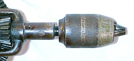
This
is the protected-spring
chuck design that was patented October
23,
1900. The springs that keep the jaws pulled back and pushed
out
against the inner wall of the shell are behind the jaws, where no
amount of poking with the drill bit can get at them. Millers
Falls used this design long after the patent ran its course of
seventeen years. |
||
|
Later
versions of the main handle had progressively
thicker waists, but the ferrules of these later handles were made from
deep drawn brass, which ought to have been stress relieved but weren't,
with the occurrence of season cracking (a military term of art)
as the consequence. The greater forces applied through the larger
capacity chucks didn't help, either. The comparisons at left are: first, Type J and Type I, and then Type I and Type H. |
||
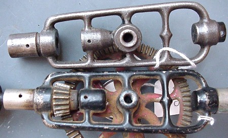 |
Note
that the Type D's frame (on top at left) now has
a connection between the rear
spindle
bearing housing and the housing of the main gear's shaft, compared to
the
unconnected spindle bearing of the older Type E
below. There was
also
a change in the shape of the side handle between these two drills, from
the "doorhandle" shape of the Type E to the smaller knob, shaped
much like the Type D's crank handle. Not only that, but the number of
teeth
in the main gear went down from 76 in the Type E's main gear to 73 in
the
Type D's gear; and the pinion lost some teeth as well, from 17 to
16. These changes came before
the
move from Millers Falls MA, to Greenfield, MA. Not only that, but
the boss originally cast into the Type E's frame to hold the main gear
has been replaced by an inserted steel shaft, whose threaded side-knob
end can
be seen at left. |
||
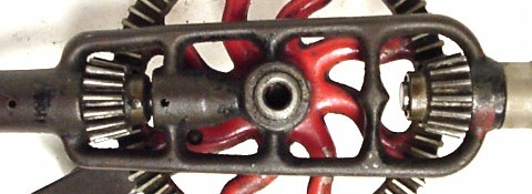
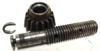
|
On
the top at left one can barely see the C-clip that retains the second
pinion
on the main-handle stud extension of the Type DC
transitional design. Also, the steel insert can be
seen
protruding from the central boss of the frame. This
was a new feature of Type
Post-E and later drills (at left). It was necessary to
spot-face the surface against which the
second pinion bears, similarly to the machining done during the
finishing of the frame for the main
pinion. In the end, this particular drill was quite unsuccessful because the main handle wobbles along with the pinion. The original LRRCW mechanism was so good for adjusting the meshing of those gears ! It isn't possible to make the stud a tight fit in the hole tapped into the frame and still assemble the pinion onto the main-handle stud. |
||
 |
The
cast iron frame used from Type M near the
beginning through Type B (at left, top) near
the end of development was finally replaced in Type A
(at
left, bottom)
with a diecast frame of a zinc-aluminum alloy known as Zamak [thanks to
Russell Davis for correcting me about the makeup of Zamak - GL].
Many manufacturers had trouble
(unbeknownst to them) with the purity of the molten metal, with the
result that the castings fell apart many years later by a
corrosion-cracking mechanism. Although this was probably the
alloy used by Millers Falls, to their everlasting credit, none of these
diecast frames has fallen into pieces. I haven't found any broken
frames made either from malleable iron or this pot metal. |
||
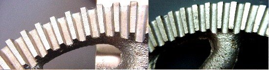 |
This
is the final stage of development. The retail
version of the
Sogard (the purchaser of the Millers Falls drill operation) drill at
right was made to a much tighter budget than was the military version
at left. The military version has nicely cut, evenly spaced
teeth. The retail version's teeth are notchy and unevenly
spaced. Either version costs far more to make than an electric
drill with greater complexity and more heavily loaded gears.
Other industries have followed a similar path. |


|
|
| Group |
Types |
Frame |
Crank Handle |
Main Handle |
End Cap |
Ferrule, Main Handle |
Side Handle |
Spindle Nose |
Thrust Brng. |
No.'s of Teeth
|
Chuck | Patent Date |
Markings |
||||
| 1 | O | Wrap-around, Robust cast iron |
Long RW peened rod |
Short, solid HardWood |
None | Short tube | None | Threaded | ? |
|
2-jaw NS |
August 14, 1877 |
Millers Falls on chuck ? |
||||
| 1a |
N |
Wrap-around, non-ferrous |
Long HW one-P |
Long, solid HardWood |
None |
Long tube | None |
? |
Cone |
|
? |
None |
None |
||||
| 1b |
M,P |
Wrap-around, Bronze or Malleable iron |
Short RW screwed |
Short, solid RoseWood |
None |
Long tube | None | Hollow | Cone |
|
None |
None |
Match Marked: 3, H or K |
||||
| 1c |
L0 |
Wrap-around Malleable
iron |
Short RW pin & washer |
Short RW lined, hollow |
Round, lignum vitae |
Long tube | None | Threaded |
Cone |
|
2-jaw NS |
August 14, 1877 |
Millers Falls on chuck |
||||
| 1d |
L' |
Wrap-around Malleable
iron |
Short RW pin & washer |
Short RW hollow |
Round, RW |
Long tube | None | Threaded | Cone |
|
2-jaw NS |
August 14, 1877 |
Millers Falls on chuck |
||||
| 1e |
L |
Wrap-around
Malleable, thicker members |
Short, ? |
Short RW hollow |
Round, lignum vitae |
Long tube | None | Threaded | Ball ? |
|
2-jaw NS |
August 14, 1877 |
Millers Falls on chuck |
||||
| 1f |
L2 |
Wrap-around Malleable, thicker members |
Short RW one-P shaft |
Long, slim, hollow RW |
Round, RW |
Long tube | None | Threaded | Cone |
|
2-jaw NS |
August 14, 1877 |
Millers Falls on chuck |
||||
| 1g |
L3 |
Wrap-around Malleable, thicker members |
Short RW one-P shaft |
Long, slim, hollow RW |
Round, RW |
Long tube | None | Threaded | Cone |
|
2-jaw NS |
August 14, 1877 |
Millers Falls on chuck |
||||
| 2a |
K1 |
Narrow ladder, LRRCW, Malleable |
? |
Long, slim, hollow RW |
Round, RW |
Short tube |
None |
Threaded | Flat |
|
2-jaw NS |
August 14, 1877 |
Millers Falls on chuck |
||||
| 2b |
K2 |
Ladder & LRRCW, Malleable |
Short RW one-P shaft |
Long, slim, hollow RW |
Round, RW | Short tube | None |
Threaded | Flat |
|
2-jaw NS |
August 14, 1877 |
Millers Falls on chuck |
||||
| 2c |
K3 |
Ladder & LRRCW, Malleable |
Short RW one-P shaft |
Long, slim, hollow RW |
Round, RW | Short tube | Egg ? |
Threaded | Flat |
|
3-jaw PS |
Never patented |
Millers Falls on chuck |
||||
| 2d |
K4 |
Ladder & LRRCW, Malleable |
Short RW one-P shaft |
Long, slim, hollow RW |
Round, RW | Short tube | Egg ? |
Threaded | Flat |
|
3-jaw NS |
Pat. App'd. For |
Millers Falls on chuck |
||||
| 2e |
K5 |
Ladder & LRRCW, Malleable |
Short RW one-P shaft |
Long, slim, hollow RW |
Flared, RW | Short tube | Egg RW |
Threaded | Balls |
|
3-jaw NS |
September 29, 1896 |
Millers Falls on chuck |
||||
| 2f |
J |
Ladder & LRRCW, Malleable |
Short RW one-P shaft |
Long, slim, hollow RW |
Flared, RW | Short tube | Egg RW |
Threaded | Balls |
|
3-jaw NS |
September 29, 1896 |
Millers Falls on chuck |
||||
| 2g |
I |
Ladder & LRRCW, Malleable |
Short RW one-P shaft |
Long, slim, hollow RW |
Flared, RW | Short, larger tube |
Egg RW |
Threaded | Balls |
|
3-jaw NS |
September 29, 1896 |
Millers Falls on chuck |
||||
| 2h |
H |
Ladder & LRRCW, Malleable |
Short RW one-P shaft |
Long, stout, hollow RW |
Flared, RW | Drawn, stepped |
Mushroom, hardwood |
Threaded | Balls |
|
3-jaw NS |
September 29, 1896 |
Millers Falls on chuck |
||||
| 2i |
G |
Ladder, LRRCW & heavy boss, Malleable |
Short RW one-P shaft |
Long, stout, hollow RW |
Flared, RW | Drawn, stepped ? |
Mushroom, hardwood |
Threaded | Balls |
|
3-jaw PS |
October 23, 1900 |
Millers Falls on chuck |
||||
| 2j |
F |
Ladder, LRRCW & heavy boss, Malleable |
Long RW one-P shaft |
Long, stout, hollow RW |
Flared, RW | Drawn, stepped |
Mushroom, hardwood |
Threaded | Balls |
|
3-jaw PS |
None | Star logo Millers Falls on crank |
||||
| 2k |
E |
Ladder, LRRCW & heavy boss, Malleable |
Long CB one-P shaft |
Long, stout, hollow CB |
Flared, RW | Drawn, stepped |
Mushroom, hardwood |
Threaded | Balls |
|
3-jaw PS |
None |
Star logo Millers Falls on crank |
||||
| 2l |
E' |
Ladder, LRRCW & heavy boss, Malleable |
Long CB one-P shaft |
Long, stout, hollow CB |
Flared, CocoBolo |
Drawn, stepped |
Mushroom, hardwood |
Threaded | Balls |
|
3-jaw PS |
None | "Since 1868" Millers Falls on crank |
||||
| 2m |
D |
Ladder, LRRCW, Malleable, beefed up |
Long CB one-P shaft |
Long, stout, hollow CB |
Flared, CB | Drawn, stepped |
Chef's Cap, cocobolo |
Threaded | Balls |
|
3-jaw PS |
None | MF No.2, Greenfield on crank |
||||
| 3a |
DC |
Ladder, LRRCW,
2ndpinion, Malleable, beefed up |
Long RW one-P shaft |
Long, stout, hollow RW |
Flared, RW | Drawn, stepped |
Mushroom ? |
Threaded | Balls |
|
3-jaw PS |
None | "Since 1868" Millers Falls on crank |
||||
| 4a |
C |
Ladder, 2nd pinion, M, beefed up |
Long CB one-P shaft |
Long, stout, hollow CB |
Flared, CB |
Drawn, stepped |
Mushroom, hardwood |
Threaded | Balls |
|
3-jaw PS |
None | MF No.2, Greenfield on crank |
||||
| 4b |
B |
Ladder, 2nd pinion, Malleable, beefed up |
Chef's Cap, CB |
Long, stout, hollow CB |
Flared, CB | Drawn, stepped |
Chef's Cap, cocobolo |
Threaded |
Balls |
|
3-jaw PS |
None | MF No.2, Greenfield on crank |
||||
| 4c |
A |
Ladder & 2nd pinion, pot metal |
Chef's Cap, CB | Long, stout, hollow CB |
Flared, CB | Drawn, stepped |
Chef's Cap, cocobolo |
Threaded | Balls |
|
3-jaw VS |
None | Millers Falls on crank |
||||
| 5a |
SoJo - R |
Ladder & 2nd pinion, pot metal |
Chef's Cap, HW |
Long, stout, hollow HW |
Flared, HW |
Drawn, stepped |
Chef's Cap, hardwood |
Threaded | Balls ? |
|
3-jaw VS |
None | 2-01: SoJo, Sogard, or Brookstone on crank |
||||
| 5b |
SoJo - M |
Ladder & 2nd pinion, pot metal |
Chef's Cap, HW |
Long, stout, hollow HW |
Flared, HW |
Drawn, stepped |
Chef's Cap, hardwood |
Threaded | Balls ? |
|
3-jaw VS |
None | Sogard USA on crank |
|
|
||||||||||||||||||||||||||||||||||||||||||||||||||||||||||||||||||||||||||||||||||||||||||||||||||||||||||||||||||||||||||||||||||||||||||||||||||||||||||||||||||||||||||||||||||||||||||||||||||||||||||||||||||||||||||||||||||||||||||||||||||||||||||||||||||||||||||||||||||||||||||||||||||||||||||||||||||||||||||||||||||||||||||||||||||||||||||||||||||||||||||||||||||||||||||||||||||||||